آزمایش چرخه ای یک قاب مهاربندی شده هم مرکز با شکل پذیری پایین در مقیاس کامل
چکیده
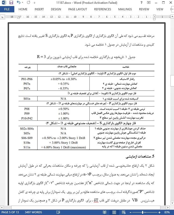
قابهای فولادی مهاربندی شده ی هم مرکز (CBF)به طور گسترده به عنوان سیستمهای مقاوم در برابر نیروی جانبی برای ساختمانهای با ارتفاع کم تا متوسط در مناطق زلزلهخیز متوسط آمریکا مانند سواحل شرقی و غرب میانه مورد استفاده قرار میگیرند. اگر چه عملکرد سازهای خوب CBF ها در مناطق لرزهای متوسط برای بارگذاری های معمول مثل باد و گرانشی(وزن) به خوبی تثبیت شدهاست، در اصل هیچ دادهای برای بارگذاری زلزله وجود ندارد. در نتیجه ی این وضعیت، یک پروژه ی تحقیقاتی برای بررسی عملکرد لرزهای CBF ها در مناطق لرزهای متوسط آغاز شد. این مقاله یک جنبه از پروژه را خلاصه میکند: یک ازمایش چرخهای در مقیاس کامل از یک CBF دو طبقه- یک دهانه با فرض R = 3 و نه به طور خاص برای مقاومت لرزهای با تمرکز بر توالی حالات حدی و رفتار سیستم مربوطه طراحی شدهاست. قاب، کمانش ترد مهاربند را در هر دو مهار موجود در طبقه ی بالایی در انحراف(جابجایی) قاب ± ۰.۳۵ % تجربه کرد. سپس شکست جوش بین مهاربند- ورق گاست در طبقه ی پایین مشاهده شد تا تاثیر تعامل مجدد مهاربند روی مقاومت سیستم بررسی شود.
1. مقدمه
شکل پذیری سیستمهای مقاوم در برابر نیروی جانبی، که از طریق تحقیق در مورد رفتار غیر خطی آنها توسعه یافته اند، به طور گسترده در مناطق زلزلهخیز استفاده میشوند. این سیستمها مانند قابهای ویژه ی مقاوم در برابر خمش(قاب خمشی) (SMRF)یا قابهای مهاربندی شده ی هم مرکز ویژه (SCBF)، که با استفاده از روشهای طراحی مبتنی بر ظرفیت با جزییات جامع مورد نیاز ایجتد شده اند،از رفتار شکننده جلوگیری می کنند. به عنوان مثال، قابهای فولادی مهاربندی شده ی هم مرکز (CBF)به دلیل نسبت سختی به وزن بالا در محدوده ی الاستیک، به طور گسترده برای ساختمانهای با ارتفاع کم تا متوسط در ساحل شرقی و میانه در ایالاتمتحده استفاده میشوند، اما عملکرد غیر ارتجاعی لرزهای آنها اساسا مطالعه نشده است.
6. خلاصه و نتیجه گیری
آزمایش کامل یک قاب دو طبقه R=3 با مهاربندی هم مرکز شورون (CBF)دادههای جدید ارزشمندی را در مورد رفتار چرخهای قابهای مهاربندی شده ارایه میدهد که به طور خاص برای مقاومت لرزهای دقیق نیستند. نواحی لرزهای معمول تا متوسط و محبوب به دلیل اقتصاد شان، قابهای R = 3 به دلیل فقدان جزییات لرزهای، بیشتر مستعد تجربه کردن وضعیتهای حدی شکننده هستند. در طول این آزمایش، هر دو مهاربندهای طبقه ی ۲ یک مکانیزم کمانش ترد با کاهش قابلتوجه مقاومت را تجربه کردند. این در مقایسه با دیگر آزمایش های مقیاس کامل انجامشده توسط نویسندگان در یک قاب مهارشده ی متمرکز معمولی R=3.25، (OCBF ) است، که رفتار کمانشی شکل پذیر بیشتری مهاربند را به دلیل الزامات جزئیات لرزهای نسبتا کم آن تجربه کردهاست [ ۴ ]. با وجود کمانش نسبتا شکننده ی مهاربند در ازمایش R = 3 که در اینجا توضیح داده شد، قاب هنوز هم ظرفیت 445 KN [ ۱۰۰ Kip ] در طبقه ی 2 با دریفت های بالاتر از 2 درصد را با شناسایی کردن ظرفیت ذخیره ی قابل دستیابی از اتصالات، عملکرد قاب و مهاربندهای کمانش یافته حفظ می کند. حداكثر برش پايه ی بدست آمده تحت پروتكل(روش) بارگذاري كه از توزيع معادل نيروي جانبي استفاده شده در طراحي بدست آمده است، 2060 KN [464 kip] بود ، تقريبا 40٪ بيشتر از برش پايه ی طراحي 1500 KN [336 kip].
Abstract
Steel concentrically-braced frames (CBFs) are used extensively as lateral-force-resisting systems for low to mid-rise buildings in moderate seismic regions of the United States, such as the East Coast and Midwest. Although good structural performance of CBFs in moderate seismic regions for typical gravity and wind loading is well-established, there is essentially no data for earthquake loading. As a result of this situation, a research project was initiated to investigate the seismic performance of CBFs in moderate seismic regions. This paper summarizes one aspect of the project: a full-scale cyclic test of a one-bay two-story CBF designed assuming R=3 and not specifically detailed for seismic resistance – focusing on the sequence of limit states and associated system behavior. The frame experienced brittle brace buckling in both upper story braces at ±0.35% frame drift. Brace-to-gusset weld fracture was subsequently induced in the lower story to observe the influence of brace re-engagement on system strength.
1 INTRODUCTION
Ductile lateral-force-resisting systems, which were developed through research documenting their nonlinear behavior, are used extensively in high seismic regions. These systems – such as special moment resisting frames (SMRFs) or special concentrically-braced frames (SCBFs), are created using capacitybased design procedures with comprehensive detailing requirements such that brittle behavior is avoided. In contrast, lateral-force-resisting systems (LFRSs) used in moderate seismic regions typically have modest or no ductile detailing requirement and capacity-based design procedures, and there is little experimental data related to the nonlinear behavior of these more brittle structural systems. For example, steel concentrically-braced frames (CBFs) are used widely for low to mid-rise buildings in the East Coast and Midwest of the United States because of their high stiffness-to-weight ratio in the elastic range, but their inelastic seismic performance is essentially unstudied.
6 SUMMARY AND CONCLUSIONS
Full-scale testing of a two-story R=3 chevron concentrically-braced frame (CBF) has provided valuable new data on the cyclic behaviour of braced frames not specifically detailed for seismic resistance. Common to moderate seismic regions and popular because of their economy, R=3 frames are more susceptible to experience brittle limit states due to lack of seismic detailing. During this test, both Story 2 braces experienced a brittle buckling mechanism with significant loss of strength. This is in contrast to the other full-scale test performed by the authors on an R=3.25 ordinary concentrically-braced frame (OCBF), which experienced more ductile brace buckling behavior as expected due to its modest seismic detailing requirements [4]. Despite the relatively brittle brace buckling in the R=3 test described here, the frame still maintained a capacity of 445kN [100 kip] to Story 2 drifts upwards of 2%, identifying the reserve capacity achievable from the connections, frame action and the buckled braces. The maximum base shear achieved under a loading protocol mimicking the equivalent lateral force distribution used in design was 2060 kN [464 kip], nearly 40% more than the design base shear of 1500 kN [336 kip].
چکیده
1. مقدمه
2. ساختمان نمونه (PROTOTYPE)
3. تنظیم آزمایشی
4. روش بارگذاری
5. مشاهدات ازمایشی
1.5. فاز ۱: الگوی بارگذاری P [ الگوی بارگذاری اصلی]
2.5. فاز دوم: الگوی بارگذاری S [تلاش برای تضعیف طبقه ی 1]
3.5. فاز سوم: الگوی بارگذاری P [از سرگیری روش بارگذاری اصلی]
4.5. فاز چهارم: الگوی بارگذاری S [ضعیف سازی طبقه 1 به صورت مصنوعی]
6. خلاصه و نتیجه گیری
Abstract
1 INTRODUCTION
2 PROTOTYPE BUILDING
3 EXPERIMENTAL SETUP
4 LOADING PROTOCOL
5 EXPERIMENTAL OBSERVATIONS
5.1 Phase I: Loading Pattern P [Original loading pattern]
5.2 Phase II: Loading Pattern S [Attempt to weaken Story 1]
5.3 Phase III: Loading Pattern P [Resume original loading protocol]
5.4 Phase IV: Loading Pattern S [Artificially weaken Story 1]
6 SUMMARY AND CONCLUSIONS
- اصل مقاله انگلیسی با فرمت ورد (word) با قابلیت ویرایش
- ترجمه فارسی مقاله با فرمت ورد (word) با قابلیت ویرایش، بدون آرم سایت ای ترجمه
- ترجمه فارسی مقاله با فرمت pdf، بدون آرم سایت ای ترجمه


