بررسی یک تنظیم کننده بهینه شده با جریان ساکن 290 Na و مصرف توان 115 Μw
چکیده
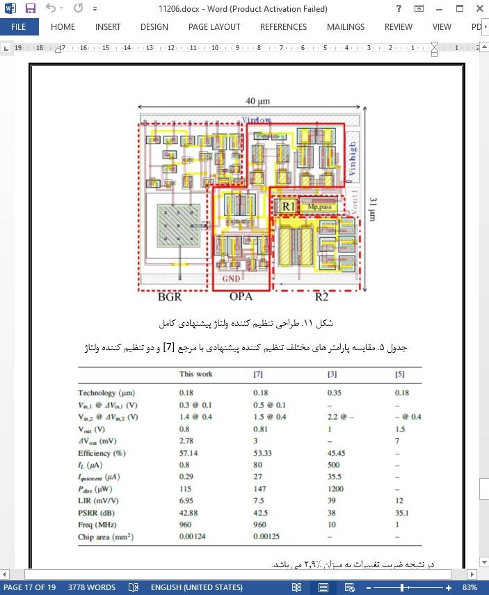
در این مقاله، یک تنظیم کننده ریپل با خروجی کم و توان کم به وسیله بهینه سازی آموزشی- یادگیری محور (TLBO) برای برنامه ها و کاربرد های شناسایی فرکانس رادیویی طراحی می شود. به منظور کاهش مصرف توان، ولتاژ زیر بلوک های تنظیم کننده از مراحل مقدماتی تامین می شود. در تشدید کننده عملیاتی پیشنهادی مورد استفاده در تنظیم کننده، اریبی تطبیقی استفاده شده و باند گپ مرجع تنظیم کننده به وسیله MOSFET طراحی می شود. جهت بهینه سازی تنظیم کننده پیشنهادی پس از مدل سازی تنظیم کننده با کمک شبکه اصلی، الگوریتم TLBO مورد استفاده قرار می گیرد. خروجی های TLBO شامل ولتاژ خروجی، مقدار ریپل و مصرف توان می باشد. با استفاده از این الگوریتم، ولتاژ خروجی به میزان 0.8 V با ریپل 2.87 Mv و مصرف توان 115Μw می باشد. همچنین جریان ساکن این طرح نیز به میزان 290Na کاهش می یابد. مساحت این چیپ طراحی در نرم افزار Cadence حدود 0.00124 mm^2 می باشد. فرکانس اجرایی این مدار حدود 960 MHz بوده و شبیه سازی با استفاده از تکنولوژی CMOS در 0.18μm انجام می شود.
مقدمه
با توجه این موضوع که تکنولوژی RFID دارای مزیت های متعددی مانند دامنه خوانش گسترده، سرعت بالا و عملیات مناسب در شرایط محیطی مختلف می باشد، این تکنولوژی می تواند جایگزین خوبی برای سیستم بارکد محسوب شود. به طور کلی تگ RFID در سه گروه فعال، غیر فعال و نیمه فعال دسته بندی می شود. در تگ غیر فعال، موج ارسال شده از سوی خواننده به وسیله آنتن تگ دریافت شده و می توان این AC را به ولتاژ DC به وسیله یکسو کننده تبدیل کرد. با توجه به این که ولتاژ خروجی یکسو کننده دارای ریپل (موج) می باشد، تنظیم کننده پس از کاهش ریپل یکسو کننده مورد استفاده قرار می گیرد.
5. نتیجه گیری
در این مقاله تنظیم کننده که از مراحل اولیه و نهایی تامین شده است برای برنامه های RFIF طراحی و بهینه سازی می شود. بهینه سازی با الگوریتم TLBO، 16 ورودی و سه خروجی انجام شده و V_out، ΔV_out و P_diss در این الگوریتم برای بهینه سازی تابع چند منظوره مورد استفاده قرار گرفته و سه خروجی به کار گرفته می شود. بر اساس نتایج به دست آمده، با در نظر گرفتن ولتاژ و بار خروجی ثابت، استهلاک توان به میزان 32μ W مستهلک شده و به میزان 115μ W می رسد، علاوه براین مقادیر جریان ماندگار و LIR معادل با 290 n A و 6.95 m V/V به کار گرفته می شوند. مساحت چیپ طراحی 0.0124 mm2 در CMOS 0.18μm می باشد.
Abstract
In this paper a low power and low output ripple regulator is designed with teaching-learning-based optimization (TLBO) for radio frequency identification applications. In order to decrease the power consumption the voltage of regulator sub-blocks is supplied from elementary stages. In the proposed operational amplifier employed to the regulator, adaptive biasing is used and bandgap reference of the regulator is totally designed by MOSFET. To optimize the proposed regulator after modeling the regulator with the help of neural network, TLBO algorithm is used. The outputs of TLBO are output voltage, ripple value and power consumption. By using this algorithm the output voltage is 0.8 V with 2.78 mV ripple and 115 lW power consumption. Also the quiescent current of this design is decreased to 290 nA. The chip area of the layout design in Cadence software is about 0:00124 mm2. The operation frequency of this circuit is 960 MHz and the simulation is done in 0:18 lm CMOS technology.
1 Introduction
Given the fact that RFID technology has the numerous advantages such as high reading range, high speed and appropriate operation in various environment conditions, this technology can be a good replacement of barcode system. In general RFID tag is categorized into three active, passive and semipassive groups. In passive tag the sent wave from reader is received with tag antenna and this AC wave can be converted to the DC voltage by rectifier. Due to this fact that output voltage of rectifier has ripple, the regulator is applied after rectifier to decrease ripple.
5 Conclusion
In this paper the regulator, which is supplied from the elementary and extremity stages, is designed and optimized for RFID applications. The optimization is done with TLBO algorithm. 16 inputs and 3 outputs, Vout, DVout and Pdiss, are used in this algorithm and for optimizing the multi-objective function, weight summation of three outputs is employed. Based on the achieved results, by considering the fixed output voltage and load, the power dissipation is attenuated about 32 lW and reached to 115 lW. in addition, the values of steady current and LIR equal to 290 nA and 6.95 mV/V, respectively. The chip area of the design is 0.00124 mm2 in 0.18 lm CMOS.
چکیده
1. مقدمه
2. ساختار تنظیم کننده
2.1 BGR پیشنهادی
2.2 OPA پیشنهادی
2.3 پیاده سازی SVR
3. شبکه عصبی و الگوریتم TLBO
3.1 شبکه عصبی
3.2 الگوریتم TLBO
3.3 الگوریتم TLBO استفاده شده
4 . نتایج شبیه سازی و مقایسه
4.1 نتایج شبیه سازی شبکه عصبی
4.2 نتایج شبیه سازی الگوریتم TLBO
4.3 نتایج شبیه سازی تنظیم کننده پیشنهادی
5. نتیجه گیری
Abstract
1 Introduction
2 The Regulator Structure
2.1 The Proposed BGR
2.2 The Proposed OPA
2.3 The SVR Implementation
3 Neural Network and TLBO Algorithm
3.1 Neural Network
3.2 TLBO Algorithm
3.3 The Employed TLBO Algorithm
4 Simulation and Comparison Results
4.1 The Simulation Results of Neural Network
4.2 The Simulation Results of TLBO Algorithm
4.3 The Simulation Results of the Proposed Regulator
5 Conclusion
- ترجمه فارسی مقاله با فرمت ورد (word) با قابلیت ویرایش، بدون آرم سایت ای ترجمه
- ترجمه فارسی مقاله با فرمت pdf، بدون آرم سایت ای ترجمه


