دانلود مقاله بررسی عملکرد مبدل های منبع نیمه امپدانس هیبرید با تغذیه فتوولتاییک خورشیدی
چکیده
ولتاژ خروجی صفحه فتوولتاییک خورشیدی معمولاً خیلی پایین است؛ مقدار این ولتاژ تحت تأثیر محیط و شرایط جوی، تا حد زیادی متغیر است. دراین مقاله ترکیب هر سیستم قدرت و خروجی مبدل های dc-dc را توسط نوعی ولتاژ ورودی افزایش یافته، تنظیم می کنیم. ساختار مبدل dc-dc برای سیستم های قدرت فتوولتاییک نیز خیلی مهم است. تکنولوژی های مختلف افزایش ولتاژ – همچون مدار یکسو کننده – در حقیقت به طور کامل آزمایش شده اند و موفق شده اند که «اندوکتانس، ظرفیت تغییر، اندوکتانس جفت شده، تطبیق امپدانس، و تکنولوژی های افزایش افزایش مارپیچی» را تغییر دهند. البته این فرآیندها هم دقت ضعیف تر و هم هزینه بالاتری دارند. اثربخشی مبدل منبع نیمه امپدانس هیبرید، بالاتر است.
1. مقدمه
در آینده نزدیک، کاهش سریع در هزینه تجهیزات انرژی الکتریکی و حذف سوخت های فسیلی، این امکان را فراهم می آورد که تا حد ممکن از انرژی فتوولتاییک خورشیدی استفاده کنیم که برای کاربردهای مختلف تولید شده است. پمپاژ آب، یک کاربرد مستقل از سیستم فتوولتاییک خورشیدی است که برق تولید میکند [4]. در حال حاضر توجه زیادی به زراعت آبی در میدان (زمین)، کاربردهای داخلی، و کاربردهای تجاری می شود. با اینکه مطالعات زیادی بر روی تولید برق ارائه فتوولتاییک خورشیدی در میدان [1] انجام شده است که از مبدل های dc-dc و محرک های موتوری مختلف استفاده می کنند، اما مبدل منبع امپدانس، همراه با یک ژنراتور DC آهنربای دائمی بدون جاروبک (BLDC) [4]، تاکنون برای ساخت چنین سیستمی به صورت مستقیم بررسی نشده است [1]. البته مبدل منبع امپدانس در برخی کاربردهای دیگر مبتنی بر ف خورشیدی نیز مورد استفاده قرار گرفته است. به علاوه توپولوژی پمپ آبی با موتور BLDC آرایه فتوولتاییک خورشیدی [2] با مبدل منبع Z ثبت شده است واهمیت آن کم و بیش مورد بحث قرار گرفته است. با این حال هیچ اعتبارسنجی تجربی انجام نشده است، هیچ مرور ادبیات جامعی نیز در زمینه نوآوری علمی موجود نیست، و اصالت مطالعات ضبط شده نیز از طریق مقایسه با توپولوژی های جاری محو شده است [3].
مبدل منبع امپدانس، یک توپولوژی مبدل نسبتاً جدید با یک ظرفیت ولتاژ باک-بوست (شکل های 1-4) است. در اینورتر کانال Z، یک فیلتر LC شبکه متقارن بین کانال های ولتاژ dc و اتصال dc، وارد می گردد. اینورتر قابلیت بوست (افزایش) یا باک (کاهش) ولتاژ در تبدیل dc-ac (تبدیل جریان مستقیم به متناوب) را دارد و میتواند ولتاژ و بسامد متغیری را در ولتاژهای خروجی تولید کند. در اینورترهای منبع Z، جریان ورودی به صورت ناپیوسته است و فشار ولتاژ در امتداد سوئیچ بیشتر است و همچنین اتصال به زمین بیشتری وجود دارد. برای غلبه بر این محدودیت ها از مبدل منبع z استفاده میشود. این در مواقعی است که منبع و بار با هم عوض می شوند [6].
5. نتیجه گیری
طرح پیشنهادی استفاده ترکیبی از شبکه های منبع امپدانس، از ترکیب شبکه های منبع امپدانس متعارف بدست می آید. شبکه های منبع امپدانس ترکیب پیشنهادی علاوه بر ظرفیت فزاینده بزرگ، تمام مزایای شبکه های منبع امپدانس سنتی – همچون جریان ورودی ثابت، و کاهش ولتاژ خط ظرفیت خازنی – را نیز حفظ میکنند. ممکن است یک ناپیوستگی برای جریان ورودی و ولتاژ، و ولتاژ جریان در سراسر شبکه منبع امپدانس متعارف وجود داشته باشد. برای حل مسئله فوق الذکر، یک شبکه منبع امپدانس اصلاح شده و یکپارچه ساخته میشود که میتوان از آن برای همان کاربردهای شبکه های منبع z متعارف با بهبود پایایی، روایی و حتی اثربخشی استفاده کرد.
Abstract
Normally the output voltage of the solar photovoltaic panel is very low; it varies widely under the influence of environment and climatic conditions. In this paper the combination of each power system and the output of the dc-dc converters are regulated by some kind of increased dc input voltage. The structure of the dc-dc converter is also very important for photo voltaic power systems. Various voltage raising technologies have indeed been thoroughly tested to date, such as rectifier circuit, managed to switch inductance, capacity to change, coupled inductance, impedance matching, and spiralled raising technologies. However, these processes are both dynamic with poor accuracy and greater cost. The effectiveness of the hybrid semi impedance source converter is greater.
1. Introduction
In the near future, the rapid decline in the cost of electrical energy equipment and the elimination of fossil fuels will allow as much use as possible of solar photovoltaic energy produced for various applications. Water pumping, the stand-alone application of the solar photovoltaic system produced electricity [4]. A great deal of attention is currently being paid to irrigated agriculture in the fields, domestic applications and commercial applications. While a number of studies have been conducted throughout the field of solar photovoltaic array [1] power generation, incorporating various Dc-dc converters and motor drives, the impedance Source converter, coupled with a permanent magnet brushless DC (BLDC) generator,[4] has not been directly explored to date for the construction of such a system. [1]. However, the impedance Source converter has been used in some other solar photovoltaic based applications. Moreover, the topology of the solar photovoltaic array [2] BLDC driven water pump with Z Source converter has been documented and its importance has been more or less discussed. However, experimental validation is lacking and there is no comprehensive literature review the scientific innovation and originality of the work recorded have been obscured by comparison with the current topologies [3].
The impedance source converter is a fairly recent converter topology with a buck-boost voltage (Figs. 1-4) capability. In the Z-channel inverter, a symmetric lattice LC filter is inserted between the dc-link and the dc-voltage channel. The inverter is capable of boosting or buck voltage in dc-ac inversion and is capable of producing variable voltage and frequency ac output voltages. In Z-source converters, the input current is discontinuous and the voltage stress across the switch is more and also there is no more ground. To overcome this limitations quazi z-source converter is used. When the source and the load are interchanged [6].
5. Conclusion
The proposed scheme use combination of impedance source networks, created by a combination of conventional Impedance source networks. Aside from the large incremental capacity, the proposed combination impedance source networks preserve all the advantages of traditional impedance source networks, such as constant input current, decreased capacitance line voltage. There may be a discontinuity of input current and voltage and current voltage throughout the conventional impedance source network. To address the above mentioned problem, a modified and integrated impedance source network is constructed which can be used for the same application as conventional z-source networks with improved reliability, reliability and even costeffectiveness.
چکیده
1. مقدمه
2. سیستم های موجود
2.1 معایب سیستم های موجود
3. سیستم پیشنهاد شده
3.1 نمودار مدار برای سیستم پیشنهاد شده
3.2 حالات عملکرد
3.3 کار کردن سیستم پیشنهادی
4. شبیه سازی و نتایج تجربی
4.1 مطلب
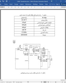
4.2 مؤلفه ها و رتبه بندی مدار شبیه سازی
4.3 نتیجه و بحث
5. نتیجه گیری
منابع
Abstract
1. Introduction
2. Existing systems
2.1. Disadvantages of existing systems
3. Proposed system
3.1. Circuit diagram for proposed system
3.2. Modes of operation
3.3. Working of proposed system
4. Simulation and experimental results
4.1. Matlab
4.2. Simulation circuit components and ratings
4.3. Result and discussion
5. Conclusion
References
- اصل مقاله انگلیسی با فرمت ورد (word) با قابلیت ویرایش
- ترجمه فارسی مقاله با فرمت ورد (word) با قابلیت ویرایش، بدون آرم سایت ای ترجمه
- ترجمه فارسی مقاله با فرمت pdf، بدون آرم سایت ای ترجمه


