
دانلود مقاله توپولوژی اینورتر بدون مبدل تک فاز با جریان نشتی کاهش یافته برای سیستم فوتوولتائیک شبکه ای متصل
چکیده
جریان نشتی نگرانی اصلی اینورترهای فوتوولتائیک (PV) بدون مبدل شبکه ای متصل می باشد. توپولوژی های اینورتر بدون مبدل تک فاز بسیاری با جریان نشتی کاهش یافته در چند سال گذشته ارائه شده اند. این ها عمدتا براساس روش های کاهش جریان نشتی به گیرش ولتاژ مد مشترک (CMV)- بدون عایق گالوانیک و گیرش CMV با عایق گالوانیک طبقه بندی می شوند. نشان داده شده است که تولید جریان نشتی شدیدا وابسته به CMV است. CMV توپولوژی های گیرش CMV- بدون نوسان می کنند و دامنه نوسان وابسته به ظرفیت اتصال سوییچ و پارامترهای پارازیتی توپولوژی می باشد. به منظور حذف کامل جریان نشتی، CMV باید درسراسر عمل اینورتر ثابت باشد. به علاوه، اینورتر همچنین باید قادر به تزریق مقدار محدودی از توان واکنشی به شبکه، طبق مقررات بین المللی باشد. در این مطالعه، توپولوژی CMV گیرشی جریان نشتی کاهش یافته ارائه می شود که می-تواند جریان نشتی را حذف کند و قادر به تزریق توان واکنشی به شبکه است. اعوجاج های هماهنگ کل (THD) جریان شبکه تزریق شده در سطح های تابش خورشیدی مختلف نیز تحلیل می شوند. به منظور تایید توصیفات تجربی، توپولوژی های پیشنهادی در محیط مطلب/سیمولینک شبیه سازی می شوند. درنهایت، نتایج شبیه سازی شده به طور تجربی اعتبارسنجی می شوند.
1- مقدمه
سیستم های PV عمدتا به صورت سیستم مستقل و سیستم شبکه ای متصل دسته بندی می شوند. سیستم مستقل توان را مستقیما برای بار یا ابزار الکتریکی تامین می کند. این با سیستم ذخیره ساز (باطری) یکپارچه می شود. در مقابل، سیستم PV شبکه ای متصل انرژی تولید شده را برای شبکه تاسیسات برای انتقال مستقیم، توزیع و مصرف تامین می کند. چونکه سیستم ذخیره سازی انرژی مورد نیاز نیست، سیستم PV شبکه ای متصل به صرفه تر است و به نگهداری احتیاج ندارد {1-5}. برای بیش از 99 درصد از توان PV نصب شده در جهان به کار می رود {6}.
براساس عایق گالوانیک، توپولوژی های اینورتر PV شبکه ای متصل به بدون مبدل و با مبدل گروه بندی می شوند. وظیفه اصلی مبدل فراهم کردن تقویت ولتاژ و عایق گالوانیک بین ماژول های PV و شبکه می باشد {7}. بنابراین، از شارش جریان dc و تزریق جریان نشتی به شبکه جلوگیری می کند {8}. مبدل می تواند وابسته به پیکربندی ماژول های PV از فرکانس پایین (LF) یا فرکانس بالا (HF) باشد. مبدل های LF سنگین، حجیم و گران هستند و این موارد کارایی سیستم را به دلیل اتلاف توان در سیم پیچ ها کاهش می دهند {9-11}. اگرچه، کاهش قابل توجهی در اندازه و وزن می تواند با استفاده از مبدل HF به دست آید. کارایی سیستم کل هنوز ناشی از چندین مرحله مبدل پایین است (dc-dc و dc-ac) {12}. ازاین رو، توپولوژی های اینورتر بدون مبدل برای کاربرد PV برای غلبه بر این مشکلات ارائه می شوند. می تواند کارایی سیستم را تا 1-2 درصد بهبود بخشد {13}. به علاوه، آن ها سبک تر، کوچکتر و کم هزینه تر می باشند.
اگرچه اینورتر PV بدون مبدل مزایای زیادی دارد، جریان نشتی بالا نگرانی اصلی است. به دلیل عدم حضور مبدل، یک اتصال گالوانیک تشکیل می شود که مسیری را برای شارش جریان نشتی از ماژول PV به شبکه فراهم می کند {10،14}. در همان زمان، خازن پارازیتی، که بین سلول های PV و قاب فلزی ماژول تشکیل می شود، اگر پتانسیل فرکانسی بالایی در آن اعمال شود، جریان نشتی بالایی را تولید می کند. جریان نشتی اعوجاج هماهنگ کل (THD) جریان شبکه، تداخل الکترومغناطیسی (EMI) و اتلاف های سیستم را افزایش می دهد و موجب مشکلات امنیت پرسنل می شود {10،11،14-17}.
8- نتیجه گیری
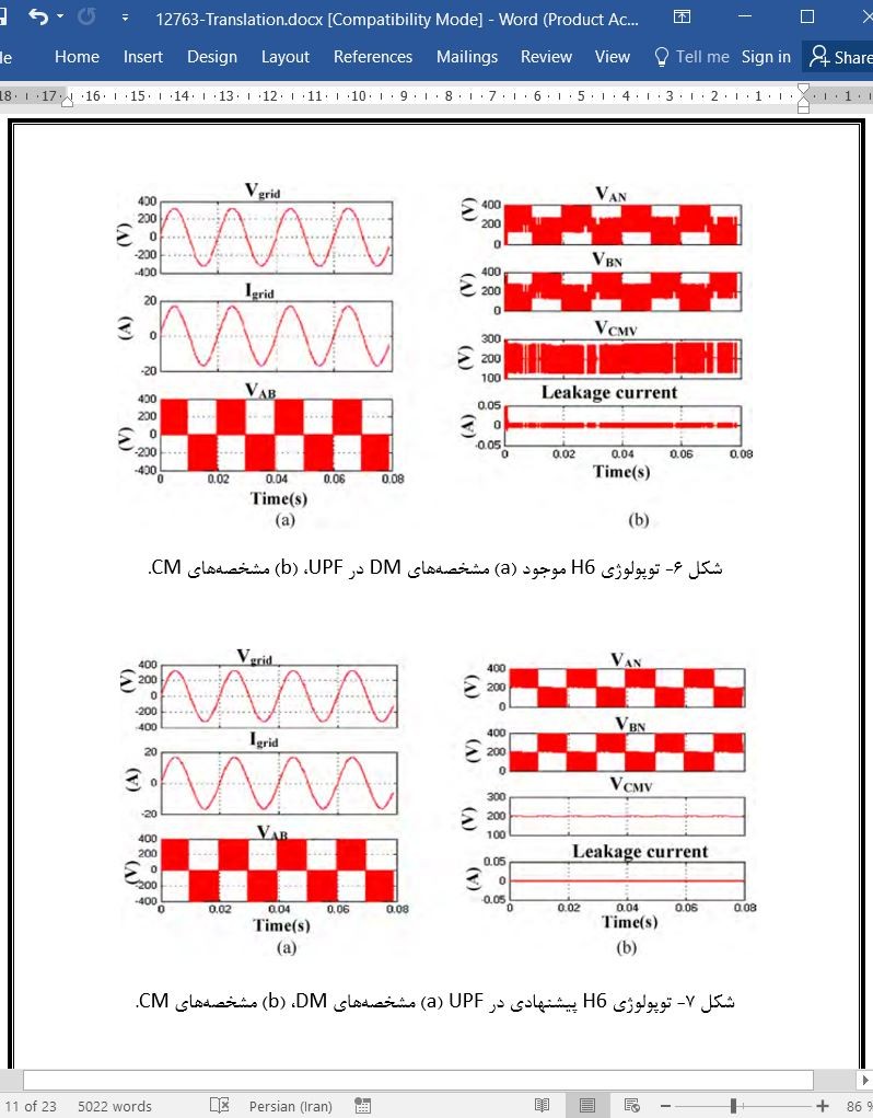
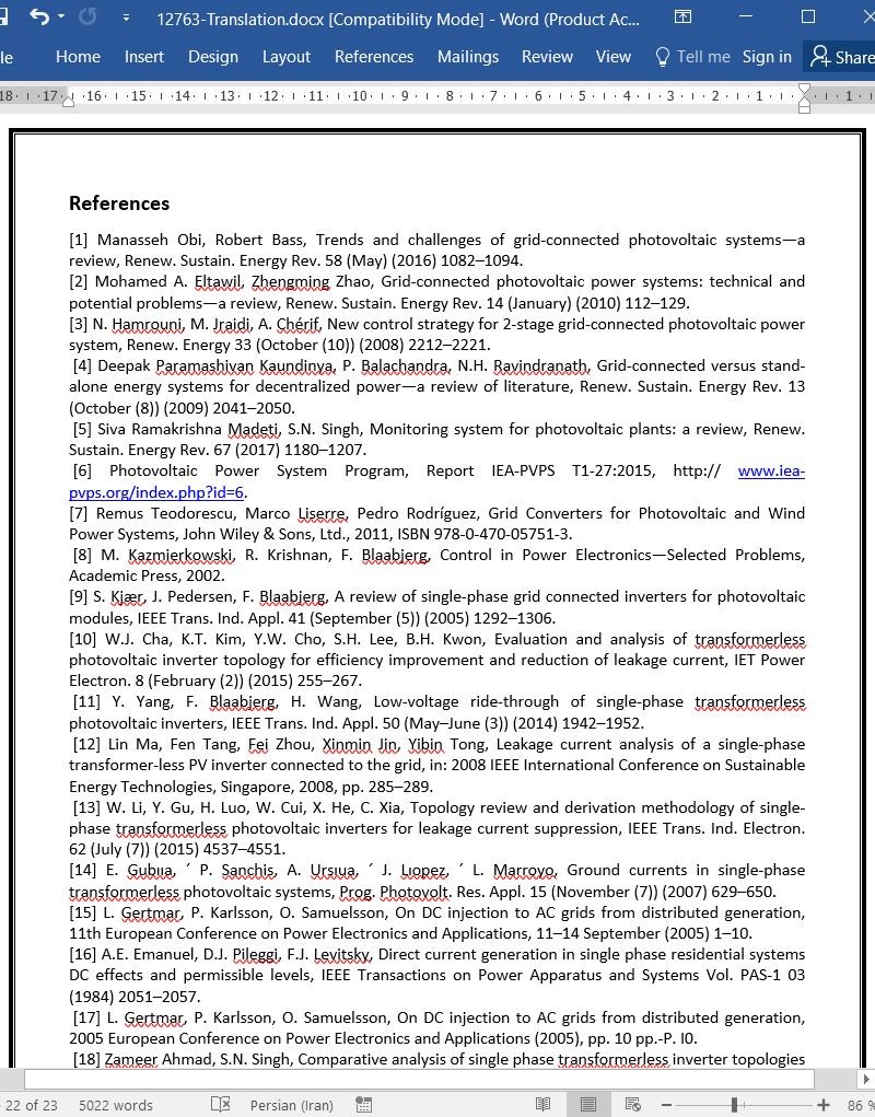
در این مقاله، توپولوژی اینورتر بدون مبدل H6CMV گیرشی برای سیستم PV شبکه ای متصل ارائه می شود. نشان داده شده است که تولید جریان نشتی وابسته به ولتاژ مد مشترک (CMV)، مخصوصا، مولفه های فرکان بالا، زیاد است. در توپولوژی H6 موجود، CMV نوسان می کند و دامنه نوسان وابسته به خازن های اتصال سوییچ است. اثر این خازن ها بر تولید جریان نشتی درطول حالت های ولتاژ صفر اینورتر قابل توجه می باشد. توپولوژی پیشنهادی CMV را به صورت نصف ولتاژ لینک dc درطول حالت های ولتاژ صفر نگه داشته است. به عنوان یک نتیجه، جریان نشتی به یک مقدار بسیار پایین کاهش می یابد و مستقل از خازن های اتصال می باشد. تحلیل عملکرد توپولوژی های H6 و H6 پیشنهادی در مطلب/سیمولینک انجام می شود و نتایج به طور تجربی اعتبارسنجی می شوند. مزیت های توپولوژی پیشنهادی به صورت زیر توصیف می شوند:
1. شاخه گیرشی بهبود یافته در توپولوژی پیشنهادی CMV را به صورت نصف ولتاژ لینک dc درسراسر عملیات اینورتر نگه داشته است. به عنوان یک نتیجه، جریان نشتی تقریبا به صفر کاهش می یابد.
2. THD توپولوژی پیشنهادی در حد مشخصی قرار دارد و مطابق با مقررات بین المللی در سطح های تابش خورشیدی مختلف می باشد. این به دلیل راهبرد مدولاسیون کاملا تک قطبی و گیرش CMV می باشد. توپولوژی موجود THD جریان بیشتر از 5 درصد را در سطح تابش خورشیدی پایین تولید می کند، که به طور قابل توجهی تولید توان را کاهش خواهد داد.
3. هیچ فیلتر CM اضافی برای خنثی کردن اثر سوییچ های خازن های اتصال مورد نیاز نیست. این می تواند چگالی توان و هزینه را بهبود ببخشد.
ازاین رو، توپولوژی اینورتر بدون مبدل H6 گیرشی فعال استخراج شده کاندید مطلوبی برای سیستم PV شبکه ای متصل با عملکرد بالا می باشد.
Abstract
Leakage current is the main concern of the grid connected transformerless photovoltaic (PV) inverters. Many single phase transformerless inverter topologies with reduced leakage current have been introduced in the past few years. These are mainly classified on the basis of leakage current reduction methods Galvanic isolation without- common mode voltage (CMV) clamping and with-CMV clamping. It has been shown that leakage current generation is highly dependent on CMV. CMV of the topologies without- CMV clamping oscillates and oscillation amplitude depends on switches’ junction capacitances and parasitic parameters of the topology. In order to eliminate the leakage current completely, CMV must be constant throughout the inverter operation. Moreover, inverter should also be capable to inject definite amount of reactive power into the grid, as demanded by the international regulations. In this study, reduced leakage current CMV clamped topology is proposed which can eliminate leakage current and capable of injecting reactive power into the grid. Total harmonic distortions (THD) of injected grid current at various solar irradiance levels are also analyzed. In order to verify the theoretical explanations, the proposed topologies are simulated in Matlab/Simulink environment. Finally, the simulated results are validated experimentally.
1. Introduction
PV systems are mainly categorized as: stand-alone system and grid connected system. Stand-alone system supply power directly to load or electrical appliance. It is integrated with energy storage (battery) system. In contrast, grid connected PV system supply generated energy into the utility grid for directtransmission, distribution, and consumption. As energy storage system is not needed, grid connected PV system is more cost effective and maintenance free [1–5]. It account for more than 99% of the globally installed PV power [6].
Based on the galvanic isolation, grid connected PV inverter topologies are grouped into transformerless and with transformer. The main functions of transformer are to provide voltage amplification and galvanic isolation between PV modules and the grid [7]. Thus, it prevents flow of dc current and leakage current injection into the grid [8]. Transformer can be of low frequency (LF) or high frequency (HF), depending on PV modules configuration. LF transformers are heavy, bulky and expensive and these reduce the system efficiency because of power loss in windings [9–11]. Even though, significant reduction in size and weight can be achieved by using HF transformer. The efficiency of the entire system is still low due to multiple converter stages (dc-dc and dc-ac) [12]. Hence, transformerless inverter topologies are introduced for PV application to overcome these issues. It can improve the system efficiency by 1–2% [13]. Furthermore, they are lighter, smaller and lower in cost.
Although the transformerless PV inverter has many advantages, high leakage current is the main concern. Because of the absence of transformer, a galvanic connection is formed which provide path for leakage current to flow from PV module to the grid [10,14]. At the same time, parasitic capacitor, which is formed between PV cells and metallic frame of module, generates high leakage current if high frequency potential is applied across it. The leakage current increases the total harmonic distortion (THD) of the grid current, electromagnetic interference (EMI) and system losses, and it causes personal safety problems [10,11,14–17].
There are mainly three modulation techniques: unipolar, bipolar and hybrid modulation, which can be used for single phase full bride (H4) transformerless PV inverter. CMV, leakage current and efficiency characteristics change according to the modulation schemes. In case of unipolar modulation and hybrid modulation three- level voltage (0→+VPV →0→−VPV →0)is generated across filter, yielding lower core loses [18]. However, they generate high leakage current because of high frequency CMV. In case of bipolar modulation two-level voltage (+VPV, −VPV) is generated, yielding higher core losses. Moreover, it generate constant CMV, hence leakage current is low.
8. Conclusion
In this paper, CMV clamped H6 transformerless inverter topology for grid connected PV system is presented. It has been shown that leakage current generation is highly dependent on common mode voltage (CMV), especially, high frequency components. In existing H6 topology CMV oscillates and amplitude of oscillation is dependent on switches’ junction capacitors. The effect of these capacitors on leakage current generation is significant during zero voltage states of inverter. Proposed topology has clamped the CMV to half of the dc link voltage during zero voltage states. As a result, leakage current is reduced to a very low value and is independent of junction capacitors. Performance analysis ofthe existing H6 and proposed topologies are carried out on Matlab/Simulink, and results are experimentally validated. The advantages of proposed topology are described as follows:
1. Improved clamping branch in the proposed topology has fixed CMVto half ofthe dc link voltage throughoutinverter operations. As a result leakage current is almost reduced to zero.
2. THD of the proposed topology is within the specified limit and complies with the international regulation at various solar irradiance levels (100–1000W/m2). This is because of fully unipolar modulation strategy and CMV clamping. The existing topology generates current THD more than 5% atlow solar irradiance level, which will reduce significant power generation.
3. No extra CM filter is required to nullify the effect of junction capacitors switches. This can improve the power density and cost.
Hence, the derived active clamped H6 transformerless inverter topology is optimized candidate for high-performance grid connected PV system.

(جهت بزرگ نمایی روی عکس کلیک نمایید)
چکیده
1- مقدمه
2- تحلیل در توپولوژی های H6 موجود
3- تولید جریان نشتی و ظرفیت های اتصال سوییچ ها
4- توپولوژی پیشنهادی و راهبرد مدولاسیون
4-1 مدهای کارکرد توپولوژی پیشنهادی
5- نتایج شبیه سازی
6- اتلاف های توان و محاسبه دمای اتصال
6-1 محاسبات اتلاف IGBT
6-2 محاسبه اتلاف دیود
7- نتایج تجربی
8- نتیجه گیری
منابع
ABSTRACT
1. Introduction
2. Analysis on existing H6 topologies
3. Leakage current generation and switches junction capacitances
4. Proposed topology and modulation strategy
4.1. Operation modes of proposed topology
5. Simulation results
6. Power losses and junction temperature calculation
6.1. IGBT loss calculations
6.2. Diode loss calculation
7. Experimental Results
8. Conclusion
References
- ترجمه فارسی مقاله با فرمت ورد (word) با قابلیت ویرایش، بدون آرم سایت ای ترجمه
- ترجمه فارسی مقاله با فرمت pdf، بدون آرم سایت ای ترجمه