
دانلود رایگان مقاله زمان بندی سوپاپ و مکانیزم کنترل لیفت سوپاپ
چکیده
یک سیستم کنترل سوپاپ نوع جدید ارائه شده است که در آن لیفت سوپاپ و زمان بندی سوپاپ به طور مستقیم توسط موتورهای الکتریکی کنترل می شوند. یک مکانیسم از سیستم کنترل زمانبندی سوپاپ از چرخ دنده های سیاره ای ساخته شده است. دنده بیرونی، قرقره زمانبندی است که دارای کمربند زمانبندی هدایت شده توسط میل لنگ یک موتور می باشد. دو چرخ دنده سیاره ای داخل قرقره می باشند. چرخ دنده ها با دنده داخلی از قرقره تعامل پیدا می کنند. مرکز دیسک، که دارای مراکز دنده های سیاره ای است، به میل بادامک متصل می شود. بنابراین، چرخش میل لنگ به میل بادامک منتقل می شود و چرخش های دنده خورشیدی به چرخش های میل بادامک اضافه می شود. این به این معنی است که زمانی که زاویه چرخش دنده خورشیدی کنترل می شود، فاز بین سوپاپ ورودی و سوپاپ دود را می توان کنترل کرد. سیستم کنترل لیفت از نوار لغزنده خطی و پیچ توپ ساخته شده است. شکل بادامک این سیستم سه بعدی است. ارتفاع بادامک در امتداد محور شفت تغییر می کند. هنگامی که پیچ توپ می چرخد، میل بادامک در جهت محوری می لغزد، به طوری که لیفت میل بادامک متغیر است. روش کنترل برای مکانیسم ارائه شده است که در آن فاز سوپاپ و لیفت به طور مداوم کنترل می شوند. آزمون های تجربی برای سیستم انجام می شوند.
1. مقدمه
زمان بندی سوپاپ متغیر (VVT) در موتورهای اشتعال جرقه خودرو برای بهبود صرفه جویی در سوخت، کاهش گاز ، و افزایش حداکثر گشتاور و قدرت مورد استفاده قرار می گیرد. تعدادی از مقالات برای اثرات استفاده از میل بادامک زمان متغیر گزارش شده است [1-9]. یک بررسی از مسائل در [1،2]، نوشته شده است، در [3،4]، تاثیرات زمان بندی سوپاپ متغیر در احتراق، مورد بحث قرار گرفت و مکانیزم و طرح های آن در [5-8] گزارش شده است، که در آن کنترل فشار نفت به کار گرفته شد. میل بادامک دوقلوی قابل تغییر در [9] توسعه داده شد. به منظور داشتن سیستم VVT کامل، قطارهای سوپاپ موتور بدون بادامک مورد بحث قرار گرفت [10-25]، که در آن حرکت سوپاپ کاملاً مستقل از حرکت پیستون با استفاده از محرک های الکترومکانیکی بود. در آن مقالات، نویسندگان مکانیزم های موتورهای بدون بادامک نوع جدید [10،11]، مزایای آن در عملیات خودرو [12]، عملیات خفه نشده قوی [13]، و مدل پویا [14] را مورد بحث قرار دادند. روش کنترل نیز در [16،17،21] برای مدل سازی و کنترل آن توسعه داده شد. تجزیه و تحلیل نیز در [17] صورت گرفته است. برای موتورهای بدون بادامک، بزرگترین مشکل این کنترل از سرعت صندلی سوپاپ می آید. باید بسیار آهسته از نویز و فرسودگی آکوستیک جلوگیری نمود. حل این مسئله، یک روش فرود نرم محرک سوپاپ الکترومکانیکی در [18،20] معرفی شده است. برای کنترل فیدبک، این سیستم به سنسورهای سرعت نیاز دارد، و یک دستگاه سنجش در [22] مورد بحث قرار گرفت. برای داشتن سیستم کنترل ارزان تر، دیسک سوپاپ حسگر نیز گزارش شده است [15،23].
لیفت سوپاپ متغیر نیز نقش مهمی در عملکرد موتور [19،24،25] ایفا می کند. کنترل های لیفت متغیر توسط میل بادامک مایع یا قابل تغییر انجام می شوند. نشان داده شده است که ترکیبی از لیفت سوپاپ متغیر و شارژ اگزوز توربو، پتانسیل قابل توجهی برای بهبود بیشتر گشتاور کم و حداکثر قدرت را در مقالات ارائه می دهد. بنابراین، موتور با زمانبندی متغیر و کنترل لیفت سوپاپ متغیر مطلوب می باشد. با این حال، محرکی که لیفت و زمانبندی را کنترل کند توسعه داده نشده است. موتور بدون بادامک دارای مزایای اشاره شده است، اما دارای معایب زیر می باشد: به توان الکتریکی بزرگ و سیستم های کنترل پیچیده و گران نیاز دارد. پس از حل این مشکلات، محرک الکترومکانیکی، که لیفت و زمانبندی در موتور های عملی را کنترل می کند، در آینده نزدیک توسعه خواهد یافت.
اگر چه سوپاپ مکانیکی (سیستم سوپاپ-CAM) دارای معایب برای کنترل زمانبندی های سوپاپ می باشد که در آثار قبلی ذکر شده است، همچنین دارای برخی از مزایا در هنگام اجرای کنترل زمان بندی مداوم سوپاپ می باشد. مزایا به شرح زیر است: زمانی که فنرهای مناسب استفاده شوند، لیفت بادامک از پروفیل بادامک پیروی می کند [26]. این بدان معنی است که با استفاده از مشخصات مناسب میل بادامک، حرکت دقیق سوپاپ بدون کنترل که در عملکرد موتور [19] مهم می باشد غیرممکن است. حداکثر لیفت میل بادامک را می توان در مقادیر بزرگ تنظیم نمود (5/9 میلی متر) به دلیل اینکه حرکت سوپاپ توسط مشخصات میل بادامک محدود می شود، سطح نویز در استفاده عملی است، و حرکت سوپاپ پایدار است. از این منظر، مقاله حاضر، یک سیستم کنترل جدید از نوع زمان بندی سوپاپ نوع جدید و سیستم کنترل لیفت سوپاپ را با استفاده از یک سیستم سوپاپ میل بادامک مرسوم فراهم می کند. همچنین دارای مزایای استفاده از سیستم سوپاپ-بادامک است. علاوه بر این، زمان بندی سوپاپ و لیفت سوپاپ به طور مداوم با استفاده از موتور DC کنترل می شوند. سیستم کنترل ساده است، و اگر چه تلفات اصطکاک وجود دارد، نیاز به هیچ منبع انرژی الکتریکی بزرگی برای کنترل نیست. برای داشتن کنترل دقیق مستمر زمان بندی سوپاپ، مقاله حاضر یک سیستم جدید کنترل زمان بندی سوپاپ مستمر را با استفاده از مکانیزم دنده های سیاره ای ارائه می دهد. در سیستم ما، چون یک موتور الکتریکی زمانبندی سوپاپ را به طور مستقیم کنترل می کند، به پمپ های فشار سیال و سوپاپ های الکترومغناطیسی [1-9] نیاز ندارند. مقاله حاضر نیز یک مکانیزم لیفت سوپاپ متغیر جدید یک موتور الکتریکی کنترل شده را ارائه می دهد که متفاوت سیستم [24،25] است. سیستم لیفت سوپاپ با سیستم کنترل زمان بندی سوپاپ ترکیب شده است. از این رو، سیستم کنونی می تواند لیفت سوپاپ و زمان بندی سوپاپ توسط موتورهای الکتریکی را به طور مستقیم کنترل کند.
2. مکانیسم سیستم کنترل سوپاپ
مکانیسم هدایت سوپاپ اساساً همانند یک موتور عرفی با سوپاپ ها و بادامک ها است، اما سیستم کنونی دارای مکانیسم های فاز و کنترل لیفت می باشد. سیستم کنترل سوپاپ کنونی شامل دو بخش می شود که یکی از آنها مکانیزم کنترل زمان بندی سوپاپ است و دیگری مکانیزم لیفت سوپاپ متغیر است.
2.1. مکانیزم کنترل زمان بندی سوپاپ
فاز اول از میل بادامک ها، در این مقاله متغیر است. شکل. 1 نشان دهنده هندسه مکانیسم زمان بندی سوپاپ حاضر است. چرخش های میل لنگ یک موتور با استفاده از یک تسمه زمان بندی و قرقره های زمان بندی به هر دو بادامک های ورودی و اگزوز منتقل می شوند. در این آزمایش، یک موتور اینورتر به جای موتور استفاده می شود همانطور که در شکل 1 نشان داده شده است. در موتور بدون بادامک، احتراقات بر عملکرد حرکت سوپاپ تاثیر می گذارند [24]، به دلیل حرکت سوپاپ به طور مستقیم توسط محرک الکترومکانیکی [10-25] کنترل می شود. در موتور بادامک سوپاپ، برای جلوگیری از جهش و پرش، فنر با جابجایی اولیه مناسب تنظیم می شود. نیروی بازگرداندن است که در آن k ثابت فنر سوپاپ و X، جابجایی فنر تحت گردش بادامک است. این نیروی باید بیشتر از نیروی اینرسی سوپاپ باشد و با یک ضریب ایمنی خاص تعیین می شود. اثرات احتراق موتور روی حرکت سوپاپ می تواند نادیده گرفته شود، زیرا در ضریب ایمنی خواهد بود. این به این معنی است که حرکت سوپاپ تحت مشخصات میل بادامک در موتورهای عرفی است [26]. بنابراین، موتور به جای یک موتور برای چک کردن عملکرد کنترل قابل اجرا خواهد بود.
در سیستم ما، قرقره زمانبندی دارای مکانیسم دنده سیاره ای در داخل است و چرخش قرقره زمانبندی به میل بادامک عبوری از چرخ دنده سیاره ای منتقل می شود. از آنجا که یک شفت دنده خورشیدی به یک موتور کنترل با استفاده از یک مکانیزم چرخ دنده کرم متصل می شود، موتور کنترل می تواند دنده خورشیدی را بچرخاند، اما گشتاور از میل بادامک به موتور کنترل توسط کرم قفل می شود. موتور کنترل به قاب موتور متصل می شود. از آنجا که موتور کنترل می تواند زاویه چرخش بادامک را تغییر دهد، زوایای بین سوپاپ ورودی و سوپاپ دود (فاز بین سوپاپ ورودی و سوپاپ دود) می تواند کنترل شود.
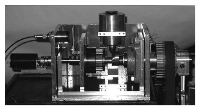
یک مکانیزم فشرده برای موتورها مطلوب است. مقاله حاضر، زمان بندی سوپاپ فشرده را فراهم می کند همانطور که در شکل 2 نشان داده شده است و این مکانیسم سیاره ای در بالا ذکر شده است. در این قرقره، دو چرخ دنده سیاره ای با دنده داخلی از قرقره فعل و انفعال پیدا می کنند. شفت های چرخ دنده های سیاره ای به یک صفحه جانبی با شفت (شفت خروجی در شکل 2) متصل می شود، و محور خروجی به میل بادامک متصل می شود. چرخش قرقره زمانبندی به میل بادامک با نسبت دنده های خاص منتقل می شود. داخل دنده سیاره ای با دنده خورشیدی درگیر می شود. دنده خورشیدی دارای یک شفت با دندانه چرخ کرم است. دنده چرخ کرم با یک کرم درگیر می کندکه شفت آن (ورودی شفت در شکل 2) دارای یک موتور کنترل (در استفاده عملی از موتور) متصل به یک قاب است. از این رو، هنگامی که موتور کنترل می چرخد، چرخش به دنده خورشیدی عبور از طریق چرخ کرم منتقل می شود. چرخش دنده خورشیدی به قرقره اضافه می شود. سپس، فاز بین سوپاپ ورودی و سوپاپ دود می تواند متغیر باشد. در این سیستم، هنگامی که موتور کنترل نمی چرخد، مکانیزم چرخ کرم و کرم، دنده خورشیدی را قفل می کند. در این شرایط، چرخش میل لنگ به میل بادامک به طور مستقیم منتقل می شود. هنگامی که کنترل فاز مورد نیاز است، موتور کنترل راه اندازی می شود و تا زمان بندی سوپاپ را بتوان کنترل کرد.
Abstract
A new type engine valve control system has been presented, in which both the valve lift and valve timing are controlled directly by electric motors. A mechanism of the valve timing control system is made of planetary gears. The outer gear is the timing pulley which has a timing belt driven by the crankshaft of an engine. Two planetary gears are inside of the pulley. The gears engage with the inner gear of the pulley. The center of the disc, which has centers of the planetary gear, is connected to the camshaft. Then, the crank rotation is transmitted to the camshaft, and rotations of sun gear are added to the rotations of camshaft. This means that when rotation angle of the sun gear is controlled, the phase between the inlet valve and the exhaust valve can be controlled. The lift control system is made of linear slider and ball screw. The cam shape of this system is three-dimensional. The height of the cam varies along the axis of the shaft. When the ball screw rotates, the camshaft slides in the axial direction, so that the lift of the cam varies. The control method is presented for the mechanism, in which valve phase and the lift are controlled continuously. Experimental tests have been carried out for the system.
1. Introduction
Variable valve timing (VVT) is used in spark ignition automotive engines to improve fuel economy, reduce NOx gas, and increase peak torque and power. A number of papers have been reported for the effects when variable timing cam is used [1–9]. A survey of the problems were written in [1,2], in [3,4], influences of the variable valve timing on the combustion were discussed, and its mechanism and designs were reported in [5–8], in which oil pressure controls were applied. The switchable twin cam was also developed in [9]. In order to have complete VVT system, camless engine valve trains were discussed [10–25], in which the valve motion was completely independent of the piston motion by using electromechanical actuators. In those papers, the authors discussed mechanisms of new type camless engines [10,11], benefits of it in vehicle operation [12], robust unthrottled operation [13], and dynamic model The control method was also developed in [16,17,21] for its modeling and control. The analysis has also been made in [17]. For the camless engine, the biggest control difficulty comes from the valve seating velocity. It should be very slow to avoid acoustical noise and wear. Solving this problem, a method of soft landing of electromechanical valve actuator has been presented in [18,20]. To make the feedback control, the system requires velocity sensors, and a sensing device was discussed in [22]. To have cheaper control system, sensorless valve actuators were also reported [15,23].
The variable valve lift also makes an important role to the performance of the engine [19,24,25]. The variable lift controls were performed by fluid or switchable cam. It was shown that the combination of variable valve lift and exhaust turbo-charging offers a considerable potential to further improve both low-end-torque and maximum power in the papers. Therefore, the engine with variable timing and variable valve lift control are desirable. However, the actuator that controls both the lift and timing has not been developed. The camless engine has advantages as just mentioned, but it has also disadvantages as mentioned below: it needs large electric power, and complex and expensive control systems. After solving those problems, the electromechanical actuator, which controls both lift and timing in practical engine, will be developed in a near future.
Although the mechanical valve (valve–cam system) has disadvantages for controlling valve timings as mentioned in the previous works, it has also some advantages when the continuous valve timing control can be performed. The advantages are as follows: the cam lift follows the cam profile when appropriate springs are used [26]. This means that, by using the appropriate cam profile, the precise valve motion is possible without control, which is also important in engine performance [19]. The maximum cam lift can be set at large values (5–9 mm) because the motion of the valve is restricted by the cam profile, the noise level is in practical use, and the valve movement is stable. From this situation, the present article provides a new-type valve timing and valve lift control system using a conventional valve–cam system. It has advantages of valve–cam system as just mentioned. In addition, the valve timing and valve lift are controlled continuously by using DC motors. The control system is simple, and although there is a friction loss, it requires no large electric power source for the control. To have precise continuous valve timing control, the present article gives a new continuous valve timing control system using planetary gear mechanism. In our system, since an electric motor controls the valve timings directly, it does not require fluid pressure pumps and electromagnetic valves [1–9]. The present article also provides a new variable valve lift mechanism controlled by an electric motor, which is different from the system in [24,25]. The valve lift system is combined to the valve timing control system. Hence, the present system can control both valve lifts and valve timing by electric motors directly.
2. Mechanism of valve control system
The driving mechanism of the valve is essentially the same as that in a customary engine with valves and cams, but the present system has phase and lift control mechanisms. The present valve control system consists of two parts, one of which is the valve timing control mechanism, and the other is the variable valve lift mechanism.
2.1. Valve timing control mechanism
The phase of one of the cams is variable in this article. Fig. 1 shows the geometry of the present valve timing mechanism. Rotations of a crankshaft of engine are transmitted to both inlet and exhaust cams by using a timing belt and timing pulleys. In this experiment, an inverter motor is used instead of engine as shown in Fig. 1. In the camless engine, combustions affect the performance of valve motion [24], because the valve motion is directly controlled by electromechanical actuator [10–25]. In the valve–cam engine, since, to prevent jumps and bounces, the spring is set with an appropriate initial displacement (x0). The restoring force is F = k(x0 + x), where k is the valve spring constant and x, the displacement of the spring under the cam rotation. The force should be greater than the inertia force of the valve, and it is decided with a certain safety factor. The effects of combustion of the engine on the valve motion can be neglected because it will be in the safety factor. This means that the valve motion follows the cam profile in customary engines [26]. Therefore, the motor will be applicable instead of an engine for checking the control performance.
In our system, the timing pulley has planetary gear mechanism inside, and the rotation of the timing pulley is transmitted to the camshaft passing through the planetary gears. Since a shaft of the sun gear is connected to a control motor using a worm gear mechanism, the control motor can rotate the sun gear, but the torque from the cam to the control motor is locked by the worm. The control motor is connected to the engine frame. Since the control motor can vary the rotation angle of the cam, the angles between the inlet valve and the exhaust valve (phase between the inlet valve and the exhaust valve) can be controlled.
A compact mechanism is desirable for engines. The present article provides a compact valve timing control pulley unit as shown in Fig. 2 that has the above-mentioned planetary mechanism. In the pulley, two planetary gears engage with the inner gear of the pulley. The shafts of the planetary gears are connected to a side plate with a shaft (output shaft in Fig. 2), and the output shaft is connected to the camshaft. The rotation of the timing pulley is transmitted to the camshaft with a certain gear ratio. The inside of planet gear engages with a sun gear. The sun gear has a shaft with worm wheel gear teeth. The worm wheel gear engages with a worm whose shaft (input shaft in Fig. 2) has a control motor connected to a frame (of engine in the practical use). Hence, when the control motor rotates, the rotation is transmitted to the sun gear passing through the worm wheel. The rotation of the sun gear is added to that of the pulley. Then, the phase between the inlet valve and the exhaust valve can be varied. In the system, when the control motor does not rotate, the worm and worm wheel mechanism lock the sun gear. In such case, the rotation of the crankshaft is transmitted to the camshaft directly. When the phase control is required, the control motor is driven, and so the valve timing can be controlled.
چکیده
1. مقدمه
2. مکانیسم سیستم کنترل سوپاپ
2.1. مکانیزم کنترل زمان بندی سوپاپ
2.2. مکانیزم لیفت سوپاپ متغیر
2.3. سنسورها
2.3.1. سنسور زاویه چرخش میل بادامک
2.3.2. سنسور لیفت سوپاپ
3. زمانبندی سوپاپ و کنترل های لیفت سوپاپ
3.1. کنترل زمان بندی سوپاپ
3.2. کنترل لیفت سوپاپ
4. نتایج تحت کنترل
5. نتیجه گیری
منابع
Abstract
1. Introduction
2. Mechanism of valve control system
2.1. Valve timing control mechanism
2.2. Variable valve lift mechanism
2.3. Sensors
2.3.1. Cam rotation angle sensor
2.3.2. Valve lift sensor
3. Valve timing and valve lift controls
3.1. Valve timing control
3.2. Valve lift control
4. Results under the control
5. Conclusion
References