
دانلود رایگان مقاله بهره برداری پایدار واحدهای فتوولتائیک برای حفظ وضعیت اتصال به شبکه
چکیده
این مقاله ابتدا ولتاژهای تغذیه ورودی مورد نیاز برای پشتیبانی از جریانها در حین خطاهای شبکه را در یک مورد سادهشده بیان میکند. در مرحله دوم با آنالیز و تحلیل، نقاط رزونانس در محل اتصال به شبکه محاسبه میشوند. تاثیر وضعیت ضعیف شبکه و تعداد زیاد اینورترها نیز ارزیابی میشوند. بمنظور تطبیق موضوع تئوری بر شرایط آزمایش اندازهگیریها مرتبط با شرایط ولتاژ پایین (LVRT) و بهرهبرداری پایدار واحد فتوولتائیک در نظر گرفته شدهاند. آنها شامل اندازهگیریها از اینورتر تکی و همچنین از واحدهای بزرگ PV در محدوده مگاوات هستند.
1. مقدمه
در بسیاری از شبکههای الکتریکی در سطح جهان، افزایش تعداد واحدهای PV نصب شده، تاثیر چشمگیر سیستمهای PV بر پایداری و کیفیت توان شبکه را به دنبال داشته است. همه شاخصها به افزایش در راستای واحدهای تولید الکترونیک قدرت تمایل دارند. واحدهای تولید خورشیدی و بادی هر دو به سطحی قابل مقایسه با نیروگاههای سنتی رسیدهاند. نه فقط در آلمان (50% از کل تولید در 21ام جولای 2013) بلکه در تمام جهان بطور منظم سهم قابل توجهی از تولید توان به منابع تجدیدپذیر تخصیص داده شده است [16]. جایگزینهای ژنراتورهای سنکرون که در راستای واحدهای تولید الکترونیک قدرت حال توسعه میباشند، باید در سطح یکسان با واحدهای تولید پایداری و توابع کنترلی را تضمین کنند. در آزمایشگاه ساخت اینورتر در سطح مگاوات Fraunhofer ISE تعداد زیادی از اینورترهای بزرگ PV با حداکثر توان نامی 1 MVA در چهار سال گذشته تولید شده است. این اندازهگیریها برای آزمایشهای حفظ اتصال به شبکه در حین خطا در واحد PV آزمایشی با ظرفیت 5 MW توسعه داده شدهاند. واحدهای تولید خورشیدی میتوانند از صدها حتی هزاران اینورتر که بصورت موازی کار میکنند، تشکیل شود؛ بنابراین نیاز جدی برای بکارگیری الگوریتمهای کنترل اینورترها وجود دارد. این مقاله در مورد ویژگیهای مختلف نقاط اتصال به شبکه واحدهای تولید توان PV با ظرفیت بزرگ و تاثیر آنها بر پایداری شبکه صحبت میکند. مشکلات حیاتی مربوط به تست بهرهبرداری در حین خطا عملکرد اینورترها در وضعیت شبکههای ضعیف را ارزیابی میکند. هر دو نتایج اندازهگیری مرتبط با LVRT و آزمایشگاهی ارائه خواهد شد. بطور خلاصه عملکرد اینورترهای امروزی در مورد نیازمندیهای سیستمهای تولید انرژی آینده و نیازهای امروزی قابل اجرا در شبکههای بینالمللی تحلیل خواهند شد.
2. رویارویی با خطاها در سیستمهای انرژی الکتریکی امروزی
A. رسیدگی به خطا در سیستم انرژی الکتریکی امروزی
بمنظور جابجایی سیستمهای انرژی الکتریکی به سمت یک شبکه با اینورترهای غالب نیاز است مسئولیتها و ظرفیتهای کنترل شبکه در جهت اینورترهای PV و توربینهای بادی تغییر کنند. پایه سیستمهای حفاظتی امروزی یک اتصال کوتاه شدید توان در سطح انتقال میباشد که با ابزار حفاظتی بصورت آرایش متوالی و پشت سرهم در نقاط اساسی اجرا میشود. این سیستم به نزدیکترین ابزار حفاظتی به محل خطا این قابلیت را میدهد که بمنظور رفع خطا عمل کند. با توجه به اندازه واحدهای تولید توان ولتاژ تغذیه ورودی به سیستم در بالاترین سطح قرار دارد و بنابراین انرژی در سطح ولتاژهای پایینتر به مصرفکنندگان انتقال داده میشود.
B. رویارویی با خطا در سیستمهای انرژی الکتریکی با ادوات الکترونیک قدرت غالب
توانایی اینورترها در تامین جریان راکتیو امکان پشتیبانی ولتاژ در حین خطا را بوجود میآورد. ابتدا تاثیر خطا بر مصرفکنندگان توان نزدیک به خطا را کاهش میدهد و سپس اینورترها در تامین جریان اتصال کوتاه مشارکت میکنند. شبکهها با بارها و واحدهای تولید الکترونیک قدرت با سهم زیاد، ساختار غیرمتمرکزی را خواهند داشت. منابع انرژی تجدیدپذیر معمولا در محدوده توان کوچکتر شکل گرفته و به منابع انرژی با تعداد بیشتری نیاز دارد. این موضوع منجر به ایجاد توان در سطح توان پایین و متوسط میشود. هر ژنراتور برپایه الکترونیک قدرت بر خلاف ترانسفورماتورها و ماشینهای چرخان قابلیت اضافه بار خیلی کم و یا فاقد این قابلیت میباشند. ژنراتورهای الکترونیک قدرت همچنین فاقد اینرسی ذاتی میباشند. سیستمهای حفاظت امروزی بر پایه یک اتصال کوتاه شدید هستند؛ جریانهای خطایی که به مقدار کمی از جریانهای نامی بیشتر هستند، تشخیص آنها توسط ابزار حفاظتی دشوار میباشد. برای تضمین رفع سریع خطا بوسیله ابزار حفاظتی شبکه هر واحد تولید از جمله منابع تولید پراکنده در سطح توزیع باید با تغذیه جریان خطا در شبکه بصورت دینامیکی شبکه را پشتیبانی کنند.
محاسبات زیر تاثیر تغذیه جریان خطا خازنی را نشان میدهند. یک شبکه ساده در شکل 1 نشان داده شده است. یک شبکه ایدهآل با یک منبع ولتاژ ارائه شده است. خطا بوسیله یک بار متغیر نشان داده شده است که در انتهای خط انتقال بلند با امپدانس سلفی قرار گرفته است. انتهای این خط نیز در کنار بار یک واحد PV به تولید میپردازد.
در حالت اول PV غیرفعال است. ولتاژ حاصل در انتهای خط انتقال توسط امپدانس خط و امپدانس خطا توصیف میشود.
تغییر امپدانس خطا با نقطهچین زردرنگ در شکل 2 نشان داده شده است. توان منتقل شده بر روی خط انتقال (توان برطرفسازی خطا) هنگامی که امپدانسها مقدار اندازه یکسانی دارند، به بزرگترین مقدار خود میرسد.
هنگامی که اینورتر فعال است، جریان بر ولتاژ در ترمینال خود تاثیر می گذارد. اگر اینورتر جریان اکتیو به خطای شبکه ترزیق کند، تاثیر آن بر روی ولتاژ شبکه قابل صرفنظر میباشد (خط قرمر در مقایسه با خط زرد رنگ در شکل2). در مدل درنظر گرفته شده، خط انتقال به نحوی در نظر گرفته شده که بتواند توان اتصال کوتاه تا 40 برابر توان اینورتر در انتهای خود را تحمل کند. این مسئله میتواند تحت عنوان نسبت اتصال کوتاه بیان شود. خطهای آبی و سبزرنگ در شکل 2 تاثیر زاویه فاز ولتاژ و توان عبوری از خط انتقال را نشان میدهد. توجه داشته باشید که یک جریان خطا بزرگ باید هر چه سزیعتر برطرف شود، در خط سبزرنگ قابل مشاهده است که فقط جریان خطا خازنی به پشتیبانی ولتاژ در شبکه سلفی کمک میکند.
اگر شبکه با الکترونیک قدرت غالب شامل تعداد زیادی از واحدهای تولید باشد، میتوان فرض کرد که بسیاری از آنها در حالت تامین بار عمل میکنند و میتوانند جریانهای خطا (جریان نامی) بزرگتر ار جریان واقعی/حال حاضر در زمان مشخص را به شبکه ترزیق کنند. این میتواند با ظرفیت اضافه بار محدود مقایسه شود. در شبکههای هوشمند با واحدهای تولید کم، نیاز است که پایداری ولتاژ (پشتیبانی ولتاژ مرتبط با جریان خازنی) بر خلاف پایداری فرکانس متعادل شود و به جریان اکتیو نیاز است.
Abstract
This paper first explains the required feed-in of voltage supporting currents during grid faults in a simplified case. Secondly, resonance points of the grid conection point are calculated analytically. The influence of weak grid conditions and large numbers of inverters is analysed. To underline the theoretical discussion on test conditions, measurements concerning Low Voltage Ride Through (LVRT) and stable operation of PV plants are presented. They comprise measurements from single inverters, as well as from large PV plants in the megawatt range.
I. INTRODUCTION
In many electrical grids worldwide, the rising amount of installed PV power entails a considerable influence of PV systems on grid quality and stability. All indicators point to an increasing trend towards power electronic generation units. Both wind and solar plants have reached power levels comparable to conventional power plants. Considerable shares of renewable generation occur quite regularly throughout the world, not only in the German grid (e.g. 50% at 2l.July 2013, [16]). The ongoing substitution of synchronous generators by power electronic driven generation units require that those generation units guarantee the same level of stability and grid control functions. At Fraunhofer ISE's Megawatt Inverter Laboratory, several dozens of large PV inverters, with a nominal power of up to 1 MY A, have been characterised during the past four years. These measurements were expanded to fault ride through field tests in a 5 MW solar test plant. Solar power stations can be built up out of hundreds to even thousands of inverters running in parallel; therefore high requirements apply to the inverter's control algorithms. This paper discusses the various characteristics of grid connection points in large scale PV power plants and their impact on the system stability. Critical issues of the Fault Ride Through Test also examines the inverters performance in weak grid conditions. We present measurement results of both Low Voltage Ride Through (L VRT) field and laboratory measurements. To summarise, the performance of today's inverters will be compared with the needs of the future energy generation system and with the requirements of currently applicable international grid codes.
II. NECESSITY OF DYNAMIC GRID SUPPORT
A. Fault handling in today's electrical energy system
The transition of the electrical energy system towards a grid dominated by inverters requires a shift of responsibility and grid control capability towards PV inverters and wind turbines. The basis of the present protective system is a high short circuit power at the transmission level combined with a cascaded and staggered arrangement of protection devices at significant knots. This allows the grid protection device, which is the closest to the fault, to react and clear the fault. Due to the size of conventional power plants, the feed-in is at the highest voltage level and the energy is transferred to the consumers via the lower voltage levels.
B. Fault handling in power electronic dominated electrical energy systems
The inverters capability of supplying reactive current allows supporting of the grid voltage during the fault. First this reduces the impact of the fault onto nearby power consumers and secondly the inverters participate in the provision of short circuit current. Grids with a high share of power electronic loads and generation units will have a highly decentralised structure. Renewable energy sources usually form blocks in a smaller power range and require higher numbers of energy sources. They often feed into low and medium voltage levels. Any power electronic based generator has no or very limited over load capability unlike rotating machines or transformers. Power electronic generators also do not have an intrinsic inertia. Today's grid protection system is based on high fault currents; fault currents slightly higher than the nominal current are difficult to detect by the protection devices. To ensure a quick clearing of faults by grid protection devices each generation unit, including the distributed ones, need to provide dynamic grid support by feeding fault current into the grid.
The following calculation shall show how effective the feed-in of capacitive fault current is. A simple grid is presented in Fig. 1. The ideal grid is represented by a voltage source. The fault, represented by a variable load, is located at the end of a long inductive transmission line. This end is also fed by a PV inverter [12].
In a fust case, the PV inverter is disabled. The resulting voltage VFAULT at the end of the transmission line is now defined by the line impedance and the fault impedance.
The variation of the fault impedance is shown in the dotted yellow line in Fig. 2. The power transferred over the transmission line (or the power dissipation in the fault) reaches a maximum when the impedances have the same absolute value.
When the inverter is enabled the current Ipv influences the voltage VFAULT at its terminals. If the inverter feeds active current into the grid fault, the influence on the grid voltage is almost negligible (red line compared to yellow line in Fig. 2). In the considered model, the transmission line is dimensioned to reach a short circuit power of 40 times the inverter power at its end. This can also be expressed in a short circuit ratio of Sshort circuit! Pinverter = 40. The blue and the green line in Fig. 2, show the influence of the phase angle of Ipv onto the voltage VFAULT and the power dissipation of the fault. Bearing in mind that a high fault current is needed to clear the fault as fast as possible, it is made visible in the green line that only capacitive fault current helps to support the grid voltage in inductive grids.
If a power electronic dominated grid consists of a large number of generation units, one can assume that many of them operate in part-load mode and can deliver higher fault currents (nominal current) than their present/actual current at the particular moment. This can be compared to a limited over-load capability. In micro grids with only few generation units, the voltage stability (voltage support corresponds to capacitive current) needs to be balanced against the frequency stability and the need for active current.
چکیده
1. مقدمه
2. رویارویی با خطاها در سیستمهای انرژی الکتریکی امروزی
A. رسیدگی به خطا در سیستم انرژی الکتریکی امروزی
B. رویارویی با خطا در سیستمهای انرژی الکتریکی با ادوات الکترونیک قدرت غالب
3. مجموعه قوانین شبکههای بینالمللی
A. مقررات بینالمللی FRT
4. محاسبه امپدانس نقطه اتصال به شکه
A. محاسبه رزونانس فیلتر LCL شبکه
B. تاثیر تعداد اینورترها بر رزونانس فیلتر LCL
C. تاثیر امپدانس شبکه بر رزونانس فیلتر LCL
D. تاثیر متوسط ولتاژ کابلکشی بر رزونانس فیلتر LCL
5. نتایج اندازه گیری LVRT
A. مقایسه شرایط تست آزمایشگاهی و تئوری
B. شبکه تست LVRT: تقسیمکننده ولتاژ القایی
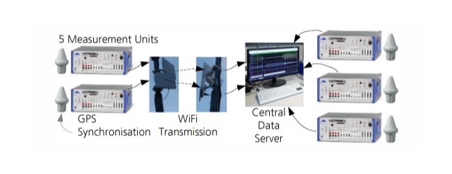
C. سیستم اندازهگیری سنکرون شده GPS
D. اندازهگیری آزمایشگاهی LVRT- شامل چند اینورتر
E. اندازهگیری آزمایشگاهی LVRT از 4 اینورتر موازی
F.اندازهگیری تئوری LVRT یک واحد خورشیدی 5 مگاواتی
6. نتایج اندازهگیری مربوط به بهرهبرداری پایدار واحد تولید PV
A. نوسانات در فرکانس رزونانس فیلتر LCL شبکه
B. نوسانات زیرهارمونیک در نقطه اتصال به شبکه
7. نتیجهگیری
منابع
Abstract
1. INTRODUCTION
2. NECESSITY OF DYNAMIC GRID SUPPORT
A. Fault handling in today's electrical energy system
B. Fault handling in power electronic dominated electrical energy systems
3. INTERNATIONAL GRID CODES
A. international Fault Ride Through Requirements
4. IMPEDANCE DETERMINATION OF GRID CONNECTION POINT
A. Calculation of LCL Grid Filter Resonance
B. Impact of the Number of Inverters on the LCL Filter Resonance
C. Impact of the Grid Impedance on the LCL Filter Resonance
D. impact of the Medium Voltage Cabeling on the LCL Filter Resonance
5. Low VOLTAGE RIDE THROUGH (LVRT) MEASUREMENT RESULTS
A. Comparison of Laboratory and Field Measurement Test Conditions
B. L VRT Testbench: Inductive Voltage Divider
C. GPS Synchronised Meassurement System
D. L VRT Laboratory Meassurement - Comparison of Multiple Inverters
E. LVRT Laboratory Meassurement of 4 Parallel Inverters
F. L VRT Field Meassurement of a 5 MW Solar Plant
6. MEASUREMENT RESULTS CONCERNING STABLE OPERATION OF PV PLANTS
A. Oscillations at LCL Grid Filter Resonance Frequency
B. Sub-harmonic Oscillations at Grid Connection Point
7. CONCLUSION
REFERENCES