
دانلود رایگان مقاله پیشگیری از ولتاژ و استراتژی کنترل هماهنگ اضطراری برای نیروگاه های فتوولتائیک
چکیده
این مقاله استراتژی پیشگیری از ولتاژ و کنترل اضطراری را پیشنهاد می کند که شامل چینش هماهنگ منابع چندگانه توان راکتیو در جهت مدیریت نوسانات ولتاژ نقطه اتصال مشترک (PCC) و پایداری در نیروگاه های PV بزرگ می باشد. هنگامی که یک اغتشاش در PCC اتفاق می افتد، ادوات جبران توان راکتیو به ترتیب اولویت برای حفظ ولتاژ PCC هماهنگ می شوند. پس از آنکه اغتشاش برطرف شد، توان راکتیو از ادوات دینامیک و سریع به ادوات استاتیک و آهسته منتقل می شود تا تولید VAR استاتیک بتواند حاشیه تولید توان را برای مقابله با اغتشاش بعدی حفظ کند. علاوه بر این، توان راکتیو خروجی اینورتر منحصر بفرد در نیروگاه های PV به طور هماهنگ با استفاده از یک مدل برای بهینه سازی توزیع ولتاژ در درون ایستگاه اختصاص داده می شود. در نهایت، اثربخشی استراتژی کنترل پیشنهادی با شبیه سازی یک نیروگاه برق PV عملی در مقیاس بزرگ مورد تایید قرار می گیرد.
1. مقدمه
با توجه به کاهش هزینه های نیروگاه های PV در سراسر جهان به دلیل کاهش متوسط قیمت فروش، ساخت و ساز نیروگاه های با مقیاس بزرگ توسط دولت ها حمایت می شود. در مقایسه با سیستم های PV کوچک و متوسط، نیروگاه های PV با مقیاس بزرگ از منابع انرژی خورشیدی به صورت موثرتری استفاده می کنند [1،2] با این حال، از آنجا که نوسانات تصادفی ازتوان خروجی و فقدان حمایت توان راکتیو در PCC معمولا یک دامنه وسیع متغیر ولتاژ PCC را منجر می شود [3-5]، نیروگاه های بزرگ PV معمولا مجبورند خودشان را به سیستم های کنترل ولتاژ و توان راکتیو مجهز نمایند.
تحت شرایط فنی الان، یک اینورتر می تواند توان اکتیو و راکتیو را جداگانه تشخیص دهد، بنابراین توان راکتیو را می توان به صورت دینامیک تنظیم کرد [6]. سرمایه گذاران PV معمولا اینورتر را در حالت عملکرد ضریب توان واحد(یک) قرار میدهند تا سود اقتصادی به حداکثر برسانند. توان خروجی راکتیو اینورترها می تواند به طور کامل مورد استفاده قرار گیرد، هزینه ادوات جبران سازتوان راکتیو دینامیک می تواند به شدت کاهش یابد [7].
چندین روش کنترل برای اینورتر ها و نیروگاه های PV ارائه شده است. در مرجع [8] یک استراتژی کنترل توان توان راکتیو ساده برای مبدل های PV تک فاز متصل به شبکه پیشنهاد شده و یک اینورتر 1-kVA برای PV جهت تکمیل عملکرد استراتژی ساخته شد. در مرجع. [9]، یک توپولوژی جدید با کارآیی بالا بدون استفاده از ترانسفورماتور برای PV متصل به شبکه با قابلیت کنترل توان راکتیو پیشنهاد شده است، و توپولوژی پیشنهاد شده می تواند توان راکتیو را در شبکه برق بدون هیچ گونه اعوجاج جریان اضافی یا جریان نشتی تزریق کند. تحقيق فوق مبناي نظري و عملي براي مبدل ها جهت مشارکت در کنترل توان راکتيو و ولتاژ در نيروگاه PV فراهم میکند. در مرجع. [10] یک کنترل شارش توان راکتیو که انتگرال توان اکتیو سیستم PV را دنبال میکند در شبکه های توزیع LV پیشنهاد میشود. در مرجع. [11]، دو روش جدید کنترل توان راکتیو که از رویکرد شبکه ای استفاده می کنند ارایه شده اند. تحقیق فوق مسئله ولتاژ اضافی در شبکه های توزیع را با استفاده از کنترل توان راکتیو برای سیستم های PV حل می کند. نویسندگان در مراجع [12-14] راه حل های کنترلی را برای ارتقاء قابلیت گذر از خطا برای نیروگاه های PV ارایه کرده اند. در مرجع. [15]، توانایی جدید DVS به عنوان یک تابعی از مبدل های PV پیشنهاد شده که از تزریق هر دو توان اکتیو و راکتیو برای بهبود پایداری ولتاژ کوتاه مدت استفاده شده است. با این حال، محققان فوق هماهنگی منابع توان راکتیو مختلف را در یک نیروگاه PV در نظر نگرفته اند.
این مقاله استراتژی پیشگیری از ولتاژ و کنترل اضطراری برای نیروگاه های PV را با هماهنگی و تنظیم منابع توان راکتیو چندگانه پیشنهاد می کند. توان راکتیو از ادوات دینامیک و سریع به ادوات استاتیک و آهسته منتقل می شود تا استراتژی قابلیت SVG توان راکتیو را به حداکثر برساند. علاوه بر این، مشکل بهینه سازی توان راکتیو به یک مدل برنامه نویسی غیرخطی شرطی تبدیل می شود. پس از حل مدل، توان خروجی راکتیو هر اینورتر بدست می آید و تخصیص بهینه توان راکتیو در میان اینورترها مشخص می گردد.
2. مشخصه های ولتاژ نیروگاه PV
یک نیروگاه PV در مقیاس بزرگ از واحدهای تولید PV (PVGUs) تشکیل شده است. از آنجایی که آرایه های PV مساحت زیادی را اشغال می کنند، فاصله بین PVGU دور است و امپدانس مجموع خطوط نمی تواند نادیده گرفته شود. مشخصه توزیع ولتاژ یک مبنای نظری برای فرموله کردن یک برنامه تخصیص توان راکتیو فراهم می کند.
2.1. توپولوژي يک نيروگاه برق PV
توپولوژی مشترک یک نیروگاه PV در مقیاس بزرگ در شکل 1 نشان داده شده است. در نیروگاه برق ,PV n مجموعه خطوط وجود دارد و هر خط تولید دارای تعدادm PVGU است.
PVGU از آرایه های PV، یک اینورتر و یک کنترل کننده متصل به شبکه تشکیل شده است. توان الکتریکی از طریق ترانسفورماتورهای محلی به مچموعه خطوط داده می شود و سپس از طریق ترانسفورماتور اصلی خارج می شود [16]. SVG و بانک های خازنی از طریق ترانسفورماتور TC به باسبار 10 کیلو ولت متصل می شوند. باسبار 10 کیلو ولت نقطه PCC است و همچنین نقطه کنترل ولتاژ است. در شکل 1 Tnm ترانسفورماتور محلی برای PVGU ها پیکربندی شده است و TC ترانسفورماتور برای ادوات جبران کننده توان راکتیو پیکربندی شده است. T ترانسفورماتور اصلی نیروگاه PV است و P + jQ توان انتقالی به خارج نیروگاه PV است.
ABSTRACT
This paper proposes a voltage prevention and emergency control strategy that consists of coordinately arranging multiple reactive power sources in order to handle the point of common coupling (PCC) voltage fluctuation and stability in large-scale PV power plants. When a disturbance occurs at the PCC, dynamic reactive power compensation devices are coordinated preferentially to support the PCC voltage. After the disturbance is cleared, the reactive power in dynamic and fast devices is transferred into static and slow devices so that the static VAR generation (SVG) can maintain a large power margin for coping with the next disturbance. Moreover, the reactive power output of the individual inverter in PV power plants is coordinately allocated using a model to optimize the in-station voltage distribution. Finally, the effectiveness of the proposed control strategy is verified by an example simulation of a practical large-scale PV power plant.
1. Introduction
With the cost of PV power plants continuously decreasing worldwide because of falling component average selling prices, the construction of large-scale PV power plants is appreciated by governments. Compared with small and medium-scale PV systems, large-scale PV power plants utilize solar energy resources more effectively [1,2]. However, since the random fluctuation of the output power and the lack of reactive power support at the PCC usually cause a large variable range of the PCC voltage [3–5], the large PV power plants are commonly forced to equip themselves with voltage and reactive power control systems.
Under the current technical conditions, an inverter can realize decoupling control of active and reactive power, so reactive power can be adjusted dynamically [6]. PV enterprises usually make the inverters operate in unity power factor mode to maximize economic benefit. If the reactive power output of the inverters can be fully utilized, the cost of dynamic reactive power compensation devices can be greatly reduced [7].
Several control methods for inverters and PV power plants have been presented. In Ref. [8], a simplified reactive power control strategy for single-phase grid-tied PV inverters was proposed, and a 1-kVA single-phase PV inverter was built to verify the performance of the strategy. In Ref. [9], a new high-efficiency transformerless topology was proposed for grid-tied PV systems with reactive power control, and the proposed topology could inject reactive power into the utility grid without any additional current distortion or leakage current. The above research provides a theoretical and practical basis for inverters to participate in reactive power and voltage control of PV power plants. In Ref. [10], a reactive power flow control pursuing the active integration of PV systems in LV distribution networks was proposed. In Ref. [11], two new reactive power control methods that exploit the networked approach were presented. The above research solves the overvoltage issue in distribution networks using reactive power control for PV systems. The authors in Refs. [12–14] proposed control solutions to enhance the fault ride-through capability for PV power plants. In Ref. [15], a novel DVS capability as a function of PV inverters that uses both active and reactive power injection to improve the short-term voltage stability was proposed. However, the above researchers did not consider the coordination of different reactive power sources in a PV power plant.
This paper proposes a voltage prevention and emergency control strategy for PV power plants by coordinately arranging multiple reactive power sources. The reactive power in the dynamic and fast devices is transferred into the static and slow devices so that the strategy maximizes the ability of SVG reactive power. Moreover, the reactive power optimization problem is transformed into a nonlinear programming model with constraints. After solving the model, the reactive power output of every inverter is obtained, and the optimal allocation of reactive power among the inverters is realized.
2. Voltage characteristics of a PV power plant
A large-scale PV power plant is composed of PV generation units (PVGUs). Since PV arrays occupy a large land area, the distance among PVGUs is far, and the impedance of collection lines cannot be ignored. The voltage distribution characteristics provide a theoretical basis for formulating a reactive power allocation scheme.
2.1. Topology of a PV power plant
The common topology of a large-scale PV power plant is shown in Fig. 1. There are n collection lines in the PV power plant, and every collection line has m PVGUs.
A PVGU is composed of PV arrays, an inverter, and a grid-tied controller. The electric power is fed into collection lines through local transformers and then transmitted outwards through the main transformer [16]. The SVG and the capacitor banks are connected to the 10 kV bus through the transformer TC. The 10 kV bus is the PCC, and it is also the voltage control point. In Fig. 1, Tnm is the local transformer configured for the PVGUs, and TC is the transformer configured for the reactive power compensation devices. T is the main transformer of the PV power plant, and P + jQ is the external transmission power of the PV power plant.
چکیده
1. مقدمه
2. مشخصه های ولتاژ نیروگاه PV
2.1. توپولوژي يک نيروگاه برق PV
2.2. ویژگی های توزیع ولتاژ یک نیروگاه PV
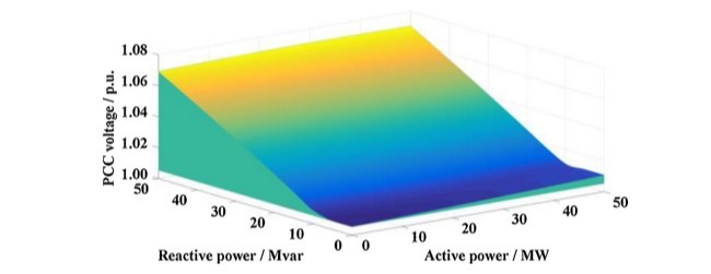
2.2.1. ولتاژ PCC یک نیروگاه PV
2.2.2. ولتاژ ترمینال PVGU ها
2.3. ظرفیت توان راکتیو اینورتر PV
2.4. مشخصه های خروجی SVG و بانک های خازنی
3. پیشگیری از ولتاژ و استراتژی کنترل هماهنگ اضطراری
3.1. چارچوب کلی
3.2. اندازه گیری و محاسبه حالت
3.3. کنترل هماهنگ ولتاژ اضطراری
3.4. کنترل هماهنگ پیشگیرانه ولتاژ
3.5. تخصیص بهینه سازی توان راکتیو در ایستگاه
4. مطالعه موردی
4.1. تجزیه و تحلیل ولتاژ PCC یک نیروگاه PV
4.2. تجزیه و تحلیل ولتاژ ترمینال PVGU ها
5. نتیجه گیری
منابع
ABSTRACT
1. Introduction
2. Voltage characteristics of a PV power plant
2.1. Topology of a PV power plant
2.2. Voltage distribution characteristics of a PV power plant
2.2.1. PCC voltage of a PV power plant
2.2.2. Terminal voltage of the PVGUs
2.3. Reactive power capacity of the PV inverter
2.4. Output characteristics of the SVG and capacitor banks
3. Voltage prevention and emergency coordinated control strategy
3.1. Overall framework
3.2. State measurement and calculation
3.3. Voltage emergency coordinated control
3.4. Voltage preventive coordinated control
3.5. In-station reactive power optimization allocation
4. Case study
4.1. PCC voltage analysis of a PV power plant
4.2. Terminal voltage analysis of the PVGUs
5. Conclusion
References