
دانلود رایگان مقاله شبیه سازی یک سیستم بادی ایزوله دیزلی با ذخیره انرژی باتری
چکیده
موضوع این مقاله، ارائه مدلسازی و شبیه سازی یک سیستم ترکیبی بادی ایزوله دیزلی(WDHS) متشکل از یک ژنراتور دیزلی (DG)، ژنراتور توربین بادی (WTG)، بار مصرف کننده، یک سیستم ذخیره انرژی مبتنی بر باتری NI-MH (BESS) و یک بار تخلیه(DL) است.BESS متشکل از یک بانک باتری و یک مبدل برق است که تبدیل DC / AC را برای واسطه گری باتری با شبکه ایزوله انجام می دهد. قابلیت های توان بالای باتری NI-MH، نیاز به تعمیر و نگهداری کم، مقاومت در برابر سوء استفاده و عدم وجود مواد خطرناک، آن را به بهترین انتخاب برای WDHS تبدیل نموده است. مدلسازی اجزای ذکر شده قبلی، ارائه می شود و عملکردWDHS از طریق شبیه سازی دینامیکی آزمایش می شود. نتایج شبیه سازی با گراف های فرکانس و ولتاژ سیستم قدرت ایزوله شده، توان اکتیو تولید شده/جذب شده توسط عناصر مختلف و ولتاژ باتری/ جریان / حالت بار الکتریکی برای بار و تغییرات سرعت باد ارائه می شود. نتایج شبیه سازی برایBESS / بدون موارد BESS مقایسه می شود که به دلیل استفاده از BESS، نشان دهنده بهبود قابل توجهی در دینامیک سیستم است.
1. مقدمه
سیستم ترکیبی دیزل بادی(WDHS) ، هر سیستم مستقل تولید برق با استفاده از ژنراتور (ها) توربین بادی(WTG) با دیزل ژنراتور (ها) (DG)برای به دست آوردن بیشترین سهم توسط منابع باد متناوب نسبت به توان کل تولید شده است، در حالی که به طور مستمر توان الکتریکی را با کیفیت بالا ارائه می کند [1]. هدف اصلی در مورد این سیستم های قدرت ایزوله شده، کاهش مصرف سوخت و بدین ترتیب، کاهش هزینه های عملیاتی سیستم و اثرات زیست محیطی است. اگرWDHS طوری طراحی شود که موتورهای دیزلی برای اجرای تمام وقت باشند، WDHS به صورت دارای نفوذ کم یا متوسط باد، بسته به نسبت نفوذ انرژی توان باد طبقه بندی می شود که به صورت زیر [2]، تعریف می شود:
نفوذ انرژی= باد توربین خروجی انرژی سالانه کیلووات ساعت
سالانه تقاضای انرژی اولیه کیلووات ساعت
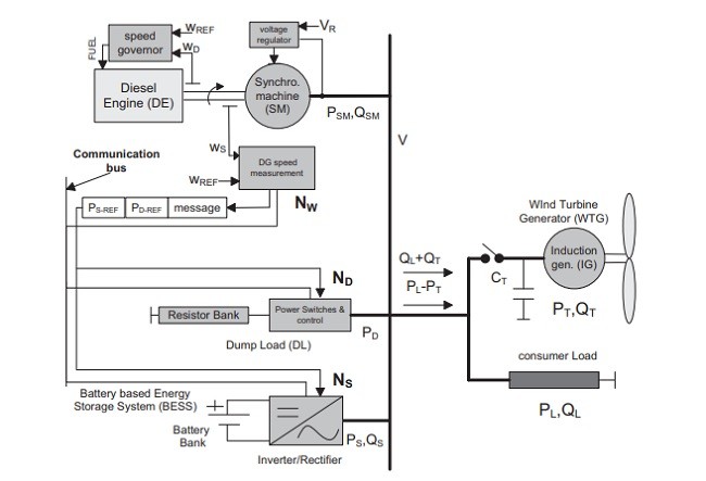
WDHS زمانی به صورت نفوذ پایین طبقه بندی می شود که(1) کمتر از 20٪ و زمانی به صورت نفوذ متوسط طبقه بندی می شود که(1) بین 20٪ و 50٪ است. برعکس اگرWDHS در خاموش نمودن دیزل ژنراتورها در طول دوره ها با دسترسی باد بالا توانمند باشد،WDHS به عنوان دارای نفوذ باد بالا طبقه بندی می شود. شکل1 نشان دهنده WDHS مطالعه شده با نفوذ متوسط در این مقاله است که در آن اجزای مندرج در تعریف WDHS می توانند دیده شوند: DG،WTG و بار مصرف کننده. سایر اجزای نشان داده شده در شکل 1 مانند بارهای تخلیه (DL) و یا سیستم های ذخیره سازی انرژی باتری(BESS) در بخش 2 توضیح داده شده اند.
مقالات متعددی در مورد موضوع شبیه سازی پویایWDHS منتشر شده است. در[3] ، یکWHDS بدون ذخیره سازی به ازای چندین آشفتگی شبیه سازی شده است، که در میان آنها ارتباطWTG به شبکه ایزوله DG قرار دارد. در [4[،WDHS مدلسازی شده شامل یک ذخیره سازی انرژی چرخ لنگر با سرعت متغیر بر اساس انتقال هیدرواستاتیک می باشد. در [5]، WDHS شبیه سازی شده با نفوذ بالا دارای یکDG با یک کلاچ است که اجازه می دهد تا رها کردن موتور دیزل (DE) از ماشین سنکرون(SM) وقتی که نیروی باد تولید شده بیش از توان مصرف شده بار باشد، میسر شود. این مقاله بر روی شبیه سازی پویایWDHS با نفوذ متوسط و بهبود پویا تمرکز می کند که برای گنجاندن یکBESS در سیستم تولید می شود. پس از این بخش مقدماتی 1، این مقاله به شرح زیر سازماندهی شده است: بخش 2، ارائه دهنده معماریWDHS بررسی شده در این مقاله همراه با الزامات کنترل آن، بخش3 ارائه دهنده سیستم های کنترل استفاده شده، بخش4 نشان دهنده مدل سازی اجزای WDHS، بخش 5 ارائه دهنده پاسخ WDHS در برابر آشفتگی های مختلف می باشند و در نهایت بخش 6 بر اثر استفاده از BESS. تاکید می کند.
2. معماری WDHS و حالت های بهره برداری
WDHS با نفوذ متوسط در شکل 1 شامل یکDG و یک WTG و دارای دو حالت عملیاتی است: دیزل تنها (DO) و دیزل بادی (WD). در حالت DO،DG ، توان اکتیو و راکتیو تقاضا شده توسط بار مصرفی را تامین می کند (در این حالت WTG خاموش است، بنابراین CT = OFF در شکل 1). اداره کننده سرعت (تنظیم سرعت+ محرک) که کنترل کننده DE است، تنظیم فرکانس را انجام می دهد و تنظیم ولتاژ توسط رگولاتور اتوماتیک ولتاژ درSM انجام می شود. در حالت WD،WTG ، همچنین توان فعال را تامین می کند و همان تنظیم کننده های حالت DO، مسئول کنترل فرکانس و ولتاژ هستند (مراجعه کنید به شکل 1، CT = ، در حالت WD).
کنترل سرعتDE در شکل 1 همزمان است به طوری که اداره کننده سرعت دیزل، نرخ سوخت رسانی لازم را برای عملDE در سرعت ثابت فرمان می دهد.DG تحت کنترل اداره کننده سرعت، تنظیم فرکانس را با حفظ تعادل لحظه ای بین توان های مصرفی و تولیدی فعال انجام می دهد. بنابراین،DE به عنوان یک منبع کنترل توان اکتیو رفتار می کند.
WTG در شکل 1 متشکل از یک توربین بادی(WT) محرک یک ژنراتور القایی (IG) به طور مستقیم وصل شده به شبکه مستقل مطابق باWTG سرعت است. توان مکانیکی تولید شده توسط WT [6] برابرست با:
PT-MEC = 1 2Av3CP
که در آن P چگالی هوا،V سرعت باد،A مساحت جاروب شده توسط پره های توربین وCP ضریب توان است. CP تابعی از نسبت سرعت TIP ((TSR = Rωr / V است که در آن R ، طول تیغه وωr سرعت شفتWT است) و گام تیغه است. از آنجا کهWTG استفاده شده در این مقاله دارای هیچ کنترل گام نیست،CP تنها تابعی از TSR است. علاوه بر این، تغییر گستره سرعتIG درWTG بسیار محدود است و در نتیجهCP را می توان به عنوان یک تابع فقط از سرعت باد در نظر گرفت. زمانی که سرعت باد، شبه تصادفی باشد، هیچ راهی برای کنترل توان اکتیو WTG وجود ندارد، بنابراین WTG به عنوان یک منبع غیرقابل کنترل توان اکتیو رفتار می کند. IG توان راکتیو را را مصرف می کند بنابراین یک بانک خازنی برای جبران ضریب توان اضافه شده است.
در حالت WD، تولید توان شده WTG ،PT می تواند بیشتر از توان مصرفی بار PL باشد، بنابراین در این مورد توان خروجی فعال از نیروگاه قدرت ایزولهPL-PT منفی است. این وضعیت به این معنی است که توانDG برای متعادل شدن توان های اکتیو باید منفی باشد (توان وارونه (DG)) (مصرف = تولید) تا فرکانس ثابت نگه داشته شود. از آنجا که اداره کننده سرعت نمی تواند DE را برای مصرف انرژی مرتبه بندی کند،DG قادر به تنظیم فرکانس نیست زمانی کهPL-PT <0 است. برای جلوگیری از توان وارونهDG ، یک بار تخلیه (DL) [7] باید برای سیستم گنجانیده شود. کنترلWDHS برایDL به منظور تخلیه توان لازم برای مثبت نگه داشتن توانDG مورد نیاز تولید شده مرتبه بندی خواهد شد، به طوری کهDG می تواند فرکانس را تنظیم نماید. DL در شکل. 1 متشکل از مجموعه ای از سوئیچ های توان و یک بانک از مقاومت ها است.ب ا بستن / باز کردن این سوئیچ برق، مصرف توان اکتیو DL می تواند کنترل شود و در نتیجه DL به عنوان یک نزول کنترل شده برای توان اکتیو رفتار می کند.
همچنین یک سیستم ذخیره سازی انرژی(ESS) [7] می تواند برای جلوگیری از توان وارونهDG در حالت WD مورد استفاده قرار گیرد. علاوه بر این ESS می تواند در هر دو حالت DO و WD به منظور کاهش نیازهای ذخیره چرخان، برای افزایش در حال بارگیری DGS به منظور بهبود عملکرد آنها و بهبود پویاییWDHS به صورتی که بعداً می بینیم، استفاده شود. سیستم ذخیره سازی انرژی بر اساس باتری(BESS) در شکل 1 متشکل از یک بانک باتری و یک مبدل توان است که تبدیل DC / AC را برای رابط نمودن بانک باتری با شبکه مستقل انجام می دهد. BESS می تواند توان را در صورت نیاز ذخیره یا بازیابی نماید، به طوری که به عنوان سینک / منبع کنترل توان اکتیو رفتار می کند. مروری برBESS را می توان در[8] دید. در[9] ، BESS برای صاف کردن توان تولید شده توسط باد استفاده می شود.
abstract
The subject of this paper is to present the modelling and simulation of an isolated Wind Diesel Hybrid System (WDHS) comprising a Diesel Generator (DG), a Wind Turbine Generator (WTG), the consumer Load, a Ni–MH battery based Energy Storage System (BESS) and a Dump Load (DL). The BESS consists of a battery bank and a power converter which performs the DC/AC conversion to interface the battery with the isolated grid. The Ni–MH battery high power capability, low maintenance, resistance to abuse and absence of hazardous substances make it the best choice for WDHS. The modelling of the previously mentioned components is presented and the performance of the WDHS is tested through dynamic simulation. Simulation results with graphs for the frequency and voltage of the Isolated Power System, active powers generated/absorbed by the different elements and the battery voltage/current/state of charge are presented for load and wind speed changes. The simulation results for the BESS/no BESS cases are compared and show a remarkable improvement in the system dynamics due to the use of the BESS.
1. Introduction
A Wind Diesel Hybrid System (WDHS) is any autonomous electricity generating system using Wind Turbine Generators(s) (WTG) with Diesel Generator(s) (DG) to obtain amaximum contribution by the intermittent wind resource to the total power produced, while providing continuous high quality electric power [1]. The main aim with these Isolated Power Systems is to reduce fuel consumption and in this way, to reduce system operating costs and environmental impact. If the WDHS is designed so that the diesels have to run full time, the WDHS is classified as being low or medium wind penetration depending on the Energy Penetration ratio of the wind power [2], defined as: Energy penetration = Wind Turbine annual energy output (kWh) Annual primary energy demand (kWh) (1)
The WDHS is classified as low penetration when (1) is less than 20% and as medium penetration when (1) is between 20% and 50%. Conversely if the WDHS is capable of shutting down the Diesel Generators during periods of high wind availability, the WDHS is classified as being high wind penetration. Fig. 1 shows the medium penetration WDHS studied in this paper where the components stated in the definition of the WDHS can be seen: the DG, the WTG and the consumer load. Other components shown in Fig. 1 such as Dump Loads (DL) or Battery Energy Storage Systems (BESS) are explained in Section 2.
Several papers have been published on the subject of WDHS dynamic simulation. In [3] a no-storage WHDS is simulated against several perturbations, among them the connection of a WTG to the DG isolated grid. In [4], the modelled WDHS includes a variable speed flywheel energy storage based on hydrostatic transmission. In [5], the simulated high penetration WDHS has a DG with a clutch which allows disengaging the Diesel Engine (DE) from the synchronous machine (SM) when the generated wind power exceeds the consumed load power. This paper focuses on the dynamic simulation of a medium penetration WDHS and the dynamic improvement that produces to include a BESS in the system. After this introductory Section 1, this article is organized as follows: Section 2 presents the WDHS architecture discussed in this article along with its control requirements, Section 3 presents the control system that has been used, Section 4 shows the modelling of the WDHS components, Section 5 presents the WDHS response against different perturbations and finally Section 6 emphasizes the effectiveness of using the BESS.
2. WDHS architecture and operation modes
The Medium penetration WDHS of Fig. 1 comprises one DG and one WTG and has two operation modes: Diesel Only (DO) and Wind Diesel (WD). In DO mode the DG supplies the active and reactive power demanded by the consumer load (in this mode the WTG is shut off so CT = OFF in Fig. 1). The speed governor (speed regulator + actuator) controlling the DE, performs frequency regulation and voltage regulation is performed by the automatic voltage regulator in the SM. In WD mode, the WTG also supplies active power and the same regulators as in DO mode are in charge of the frequency and the voltage control (referring to Fig. 1, CT = ON in WD mode).
The DE speed control in Fig. 1 is isochronous so the diesel speed governor will command the necessary fuelling rate to make the DE run at constant speed. The DG under the control of the speed governor performs the frequency regulation by maintaining an instantaneous balance between the consumed and produced active power. Therefore, the DE behaves as a controlled source of active power.
The WTG in Fig. 1 consists of a Wind Turbine (WT) driving an Induction Generator (IG) directly connected to the autonomous grid conforming a constant speed stall-controlled WTG (no pitch control). The mechanical power produced by a WT [6] is: PT-MEC = 1 2Av3CP
where is the air density, v is the wind speed, A is the area swept by the turbine blades and CP is the power coefficient. CP is a function of the Tip Speed Ratio (TSR = Rωr/v, where R is the blade length and ωr is the WT shaft speed) and the blade pitch. Since the WTG used in this paper has no pitch control CP is only a function of TSR. In addition, the IG speed range variation in the WTG is very limited and thus CP can be considered as a function only of the wind speed. As the wind speed is quasi-random there is no way to control the WTG active power, so the WTG behaves as an uncontrolled source of active power. The IG consumes reactive power so a capacitor bank has been added to compensate the power factor.
In WD mode, the WTG produced power PT can be greater than the load consumed power PL, so in this case the outgoing active power from the isolated power plant PL − PT is negative. This situation means that the DG power must be negative (DG power inversion) to balance active powers (consumption = production) in order to keep frequency constant. Since the speed governor cannot order the DE to consume power, the DG is unable to regulate frequency when PL − PT < 0. To avoid the DG power inversion, a Dump Load (DL) [7] must be incorporated to the system. The WDHS control will order to the DL to dump the necessary power to keep the needed DG produced power positive, so that the DG can regulate the frequency. The DL in Fig. 1 consists of a set of power switches and a bank of resistors. By closing/opening these power switches, the DL consumed active power can be controlled and thus the DL behaves as a controlled sink of active power.
An Energy Storage System (ESS) [7] can also be used to prevent the DG power inversion in WD mode. Additionally ESS can be used in both DO and WD modes to reduce the spinning reserve needs, to increase the loading of the DGs in order to improve their performance and to improve the dynamics of the WDHS as it will be seen later. The Battery based Energy Storage System (BESS) of Fig. 1 consists of a battery bank and a power converter which performs the DC/AC conversion to interface the battery bank with the autonomous grid. The BESS can store or retrieve power as needed, so it behaves as a controlled sink/source of active power. A review on BESS can be seen in [8]. In [9] a BESS is used for smoothing the generated power by a wind farm.
چکیده
1. مقدمه
2. معماری WDHS و حالت های بهره برداری
3. سیستم کنترل
4. شماتیک شبیه سازی
5. نتایج شبیه سازی
6. نتایج
Abstract
1. Introduction
2. WDHS architecture and operation modes
3. The control system
4. Simulation schematics
5. Simulation results
6. Conclusions