
دانلود رایگان مقاله یکپارچه سازی سلول سوختی
چکیده
پردازنده های سوخت (FPs) با پردازنده سلول های سوختی (FCS) تولید برق در محل یکپارچه شده اند. فن آوری فرآیند که در FP ها به کار گرفته شده است باید به درستی و بر اساس ویژگی های سوخت و تحمل ناخالصی و مشخصات عملیاتی انتخاب شوند. پارامترهای شیمیایی، حرارتی و فرایند مورد نظر برای اطمینان از ادغام FP-FC نیاز به توجه دقیق و به موقع دارند. شیمی و مهندسی واکنش کاتالیستی تولید H2 در FP ها و استفاده از آن در electrocatalysis چالش های عمده ای فراهم می کند. تنظیمات راکتور، میزان کوچک بودن شان و هیدرودینامیک داخلی آن ها و سایر عوامل طراحی برای یکپارچه سازی مناسب نیاز است که در نظر گرفته شود. این مقاله در حال حاضر دانش مهندسی در یکپارچه سازی FP ها را بیان می کند و همچنین چشم انداز آینده-FC برای دستیابی کارآمد به FP-FC برای استقرار در مقیاس بزرگ را بیان می کند.
مقدمه
اگرچه منابع سوخت مانند متانول یا گاز طبیعی را می توان به طور مستقیم در سلول های سوختی که در طبیعت قرار دارند مورد استفاده قرار داد، سیستم های اینچنینی دارای اشکالاتی هستند، که می توان به چگالی انرژی کمتر و بهره وری عملیاتی، سینتیک اکسیداسیون آهسته از بسیاری از هیدروکربنی سوخت های کربنی و نیاز به تصفیه گسترده به حذف ناخالصی نامطلوب، اشاره کرد. سلول های سوختی که پردازنده های جدای سوختی (FP) را درگیر میکند موارد اولیه سوختی ممکن کسترده ایی را فراهم می کند که برای تولید هیدروژن با خلوص مناسب برای سلول سوختی به کار می روند. ادغام FC-FP سطح رضابت و مقبولیت زیادیی را به وجود آورده است. همچنین، از موانع موجود در توسعه زیرساخت های گسترده هیدروژن برای FCs ها، منجر به همکاری و یکی شدن اصلاح تسهیلات درفرم FPS شده است. مورد یاد شده شامل تله گوگرد، واحد تغییر آب و گاز سیستم های مناسب پاکسازی CO که برای تولید هیدروژن از منبع هیدروکربن سلول های سوختی با MA (FC) برای تولید در محل می باشد استفاده می شود. بهره وری عملیاتی آنها بستگی به مواد شیمیایی، حرارتی، ملاحضات دینامیک، FP و تنظیمات سیستم FC و سایر ناخالصی ها عوامل مختلف دارد. به طور کلی اجزای FC شامل 33% از فضا و هزینه عملیاتی می شود. سیستم های FC-PC شامل چالشهای صنعتی زیادی می باشند. مقالات چاپ شده در این زمینه برای یک بررسی مناسب اندک و ناکافی می باشد. این مقاله مروری بر وضعیت موجود و کنونی تکنولوژی FP و FC می باشد و همچنین شامل فاکترهای کلی که بر یکپارچه سازی و تکنولوژی های آینده آنها اثر می گذارد میکند وبه دنبال این است که آیا این عوامل آنها را پربازده تر و آسانتر می کند.
2. ویژگی های اساسی سیستم های FP وFC
2.1 طبقه بندی و مشخصات FC
FC در واقع یک دستگاه الکتروشیمیایی می باشد که انرژی سوخت یک هیدروژن شبه سوخت را به طور مستقیم به انرژی اکتریکی تبدیل می کند. تکنولوژی های FC توجه زیادی را در سراسر دنیا به خود جلب کرد که واین توجه به توسعه نیرگاه های جدید، خودرهای پیل سوختی و واحدهای قدرت معطوف می شد. FC ها بر اساس نوع اکترولیت به کار گرفته شده در آنها و همچنین دمای کاری آنها و نوع سوخت و اکسیدی که در آن به کار می رود دسته بندی می شوند. ]2[ موارد مهم شامل AFC، PEFC,PAFC,MCFC و SOFC می باشد. آنها بر اساس کاربردشان و مناطق به کارگیریشان در مراحل مختلف توسعه بازاری می باشند. در این بین AFC ها در معموریت های فضایی به کار بسته شدند و همچنین بسیار گران هستند چرا که آنها به هیدروزن و اکسیژن خالص برای راه اندازی نیاز دارند. PEFC ها و PEMFCها که کوچکترین و سبک ترین طراحی ها محسوب می شوند در سیستم های جایجایی و به طور خاص برای خودروهای التریکی به کار گرفته می شوند. پیشرفت های اخیر در PEMFCهای دما بالا رسیدن به بازده های بالا را امکان پذیر کرده اند و هچنین باعث افزایش استفاده از سوخت شده اند. حد تحمل CO در آنها بین 3000 و 5000ppm با ماندگاری غشایی 20000h می باشد. آنها به محیط مرطوب شده نیاز ندارند و بسیار کمتر از انواع مشابه دما پایین شان هستند. با افزایش انعطاف مصرف سوخت و سطح تحمل ناخالصی بالاتر، MCFC ها و SOFCهایی که در دماهای خیلی گرمتر کار میکنند، از نظر مقدار گرمای تولیدی اضافی بیشتر برای نیروگاها به صرفه تر می باشند. جدول 1 مشخصات FC را معیین می کند که بر اساس دمای کارکرد، بازده انتقال انرژی، بازه کاربرد توان، مناطق کاربرد و تحمل الودگی در هیدروژن مصرفی می باشد. مواد مصرفی آنها نوع کاربرد و تنوع کابردشان را معین می کند. مهندسی واکنش این FC ها به فهم ذات دینامکی غیر خطی آنها و انتقال حرارت وجرم کمک می کند.]5[ حساسیت کاتالیس فلزی استفاده شده در انها و تحمل الودگی آنها اثر عمیقی دارد در حالی که باعث پیشرفت یکپارچه سازی FP-FC می شود. آنها به امکاناتی نظیر مانفولد، مبدل حرارتی، مرطوب کننده ها، چگالنده، شیرها، فبلترها نیاز دارند. هر کدادم از این کاربردها نیاز به سخت افزار مختص خود و همچنین نرم افزار خاص خود می باشد برای اینکه به بهبنه ترین عملکرد برسد.
2.2 شیمی FP و تکنولوژی فرایند
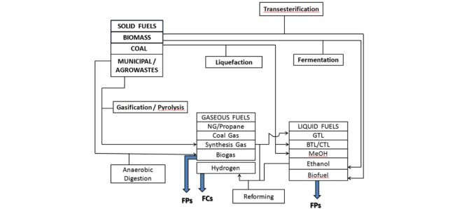
FP ها می توانند تعداد زیادی از گازها، مایعات و جامدات را به عنوان سوخت با هیدروزن به عنوان یک کاهنده معمول استفاده کنند. قیمت روبه رشد سوخت و قوانین سخت تولید و نشت GHG نیار برای جستجو موارد سوخت های سازگار با محیط زیست را تشدید کرده است. ]7[ شکل 1 نشان دهنده کربن اولیه کمتر و موارد سوخت ثانویه را شامل می شود. مورد آخری به عنوان منبع انرژِی برای FP ها به کار بشته شده است. سیستم های FP-FC برای گرما، هیدروژن و قدرت بر پایه گازهای غنی هیدروژن از فاضلاب غیر آیروبیک به کار گرفته شدند. در بین اکسیژنت ها، متانول (SE:5.5 and ED:4.4) سوخت محبوب برای اصلاح می باشد چراکه نیازمند فرایند معمول می باشد و همچنین دارای توان بالقوه برای دستیابی به بازده هی تبدیل بالا می باشد. اتانول بخاطر خاصیت دوست دار محیط بودنش و پایداری خوبش در معرض توجه قرار دارد. در میان گازها ، گاز طبیعی (SE:13.9 and ED:2.3) ، پروپان و LPG سوخت های بسیار مهمی برای FP ها می یاشند چرا که آنها در مقدار زیادی وجود دارند و همچنین بازده بالایی نیز دارند. آقای لی و همکاران ]8[ ، یک FP گازی شامل یک اصلاح کننده و یک راکتور تغیییر گاز آب طراحی کردند که بسیار کوچک و کم حجم بود. گرچه، بنزین و دیزل (SE:12.6 and ED:10.6) به خاطر بالا بودن انرژی ویژه شان بسیار مورد توجه قرار دارند وچندین مشکلات S&T برای به کارگیری آنها باید بز طرف شود. سوخت های بیومس (SE:4.2 and ED:3.0) و دیگر سوخت های جامد به حاطر زیست تخریب پذیری و خاصیت تجدید پذیری بسیار مورد اهمیت هستند. سوخت های سنتزی مایع از زغال سنگ، بیومس و گازهای طبیعی توسط روشهای مستقیم و غیر مستقیم تولید می شوند. بیومس های چوبی می توانند پیرولایزد شوند که منجر به تولید روغن های می شود و همچنین دی اکسیژن می شود که منجر به تولید سوخت مخصوص FC می شود.
پردازشگرهای سوخت باید به درستی طراحی شوند به منظور اینکه یک منبع هیدروزن برای FC مشخص شده را به وجود آورد واین در حالی است که سوخت ثانویه مشخص شده است (شکل 1). آنها شامل مواد ناخاسته ایی اهستند که باید جدا شوند ونیاز به فرابندهای متعاقب دارد. این سوخت ها برای اصلاح متفاوتند. فرایندی که بسیار استفاده شده است فرایند اصلاح بخار برای تولید گاز سنتز شده با H2/CO می باشد. نوع اصلاح گرمایی خودکار اصلاح یک فرایند گرماگیر با یک فرایند گرماده که همان واکنش اکسایش می باشد که یک توازن دمایی ایجاد شده را به کار میگرد. مورد اصلاح بخار زمان شروع زیادی را می طلبد که نسبت به حالت گرمایی خودکار سنجیده می شود. به حرحال علضت های هیدروژن بالای 75 درصد در مقایسه با 50 درصد به دست می دهد که توسط یک فرایند گرما-خودکار تولید شده است. حظور سموم کاتالیست در سوختهایی که به فراندهای اصلاح اضافه می شود نیز عامل مهم دیگر می باشد که باید بدان توجه کرد. اصلاح افزایش یافته جدبی، یک تکنولوژی جدید برای تولید هیدروژن از هیدروکربن ها با حالت جذب Co2 می باشد. انتقال یون 11 اصلاح غشاء یک پلترفرم جدید برای گازهای جدید به عنوان سوخت بوده است که شامل جداسازی هوا و اکسایش جزئی می باشد. یا اصلاح گرمایی خودکار در یک غشاء راکتور می باشد. اصلاح کننده های گازی پلاسما از کاتالیست های فلزات نجیب خودداری می کنند که این امر برای بنزین و گازهای طبیعی به کار بسته می شود. اجزای اصلی تکنولوژی یاد شده شامل الکترود ها و نازل های میکروویو برای تولید می باشند. در این مطالعه فرایند اصلاح نوسان فشارنیز همچنین معرفس شده است/ 13
در عمل طرح واکنش کلی برای اصلاح هیدروکربن سوختها به هیدروژن شامل ترکیبی از 4 واکنش دیگر همراه با اصلاح که شامل، اکسیداسیون جزئی کاتالیستی، واکنش تغییر آب-گاز، اکسیداسیون ترجیحی CO و methanation می باشد. سیستم FP جمع و جور نیاز به یک ترکیب اصلاح و کاتالیزور اکسیداسیون جزئی به منظور جلوگیری از هر گونه منبع خارجی گرما دارد، که این امر برای فرایند اصلاح گرماگیر می باشد. یکی دیگر از عملیات ها که قبل از اصلاح CO C2-C6 برای هیدروکربن مناسب است، هیدروکراکینگ است که منجر به اصلاح ویژگی های اساسی می شود. گزینه های وجود دارند که داری فن آوری پیشرفته زیادی هستند و درعین حال در دسترس هستند، و برای اصلاح در مقیاس کوچک FP-FC برای سیستم های قابل حمل مناسب هستند. اوگدن با یک بررسی[10]پتانسیل آنها را برای یکپارچه سازی با FCS نشان داده اند.
حذف CO از reformate برای رعایت حد مجاز FCS یکی از چالش های عمده ای از ادغام FP-FC است. واکنش تغییراب- گاز (WGSR) CO را به گونه ایی تغییر می دهد که به شکل CO2 و H2 دربیاید و این روش یاد شده برای حذف CO از reformates به میزان 0.5-1٪ به کار گرفته می شود. این دمای واکنش حساس است و اغلب به عنوان دمای بالا (1C 350) و دمای پایین (190-210 1C) گزینه مناسبی می باشد. اهنی که توسط کاتالیزور اکسید کروم و اکسید روی / اکسید آلومینیوم بهبود پیدا کرده است در HTS و LTS گزینه های مناسبی هستند وبه کارگرفته می شوند. غشاء معدنی که با فلزنجیب پوشش داده شده در WGSR استفاده می شوند که برای بهبود جداسازی هیدروژن با خلوص بالا به کار گرفته می شود. بررسی های بیشتر در این حوزه اخیرا [14] توسط نویسندگان حاضر منتشر شده است. تکنولوژی اکسیداسیون ترجیحی CO در یک کاتالیست ناهمگن برای کاهش آن به سطح 10 پی پی ام مقدار اکسیژن بیشتری به کارمی گیرد(ضریب 2). از طرف دیگر استراتژی کنترل و ابزار دقیق فرآیند به کارگرفته شده باید مشخص شود.[15[ متاناسیون کاتالیستی CO گزینه ای برای خالص سازی وغنی سازی هیدروژن مخلوط های گازی می باشد[16].که این مورد اصلاح معکوس بخار متان است که بدون نیاز ازهوا اتفاق می افتد. مکانیزم یاده شده درواقع اصلاح معکوس بخار متان بدون نیاز هوا می باشد . غلظت CO می تواند از 0.5٪ به کمتر از 20 کاهش می یابد. تبدیل گاز در دمای بالا وپیرولیز کردن گاز از سوخت جامد که همراه با اصلاح کاتالیزوری محصولات گاز / مایع است از جمله گزینه های فنی برای FPS است [17]. به دلیل مشکل در volatilizingکردن سوخت بر اساس زیست توده ، فن آوری بر اساس فاز اصلاح آب و اکسیداسیون آب فوق بحرانی بسیار مورد توجه قرار گرفته است[18].
ازنقطه نظر ملاحظات مهندسی، سیستم های FP متشکل از سه راکتور لوله ای مدل به عنوان یک راکتور جریان پلاگین همدما با حداقل حرارت و انتقال جرم محوری تعریف می شود. مکانهای کاربرد محلی خودرکار مکان محدودیت هایی شدید برای حجم آنها به وجود می آورد. Kolavennu و همکاران [19] استراتژی های طراحی شان را گزارش دادند.
2.3 شانس های بازار FC و FP
اولین موفقیت تجاری صنعت پیلسوختی در 2007 به دست آمد. [20.21]. رشد قابل توجهی در فروش جهانی بائو FC سالانه از آن به بعد گزارش شد. محموله جهانی شامل80،000 واحد بود که (63٪ حالت ساکن، 33٪ به صورت قابل حمل و 4٪ جابجایی بود) در سال 2012 بود که بیش از سه برابر در سال 2012 شاهد رشد بود. ظرفیت این واحد نصب شده چیزی در حدود 180 مگاوات بود. این به دلیل افزایش در رشد واحد برق و حرارت ترکیب شده و قابل حمل مصرف کننده گان و همچنین استفاده از شارژر های قابل حمل الکترونیک تو سط آنها می باشد. برنامه های کاربردی در بازار اولیه جابجایی مواد، پشتیبان قدرت، CHPs مسکونی و بسته قابل حمل قدرت و تا سال 2011 به دست آمده است. به حرحال، کاربرد سلول سوختی در بخش حمل و نقل در ادامه به هزینه و فشردگی در نوسان محدودیت هایی را شاهد بود واین برخالاف موفقیتها پردازش فن آوری بوده است. سیستم های PEMFC که مبتنب بر UPS هستند اکنون به صورت تجاری در دسترس هستند که از 65 W تا 400 موجود می باشند. سیستم های برق 1 مگاوات که براثاث PEMFCs می بودند در شمال امریکا به صورت تجاری درآمده است. ترکیبی حرارت و برق سیستم پیلسوختی مسکونی بر اساس LPG که در محدوده 1 کبلووات کار می کنند، در دانمارک به کار گرفته شده اند. ماژول های برق سلول سوختی (75 W-150 کیلو وات) برای اتوبوس هیبریدی در در شمال و جنوب امریکا و غرب اروپا استفاده می شد. با اشاره به FPS، تولید و اصلاح کوچکتر سیستم های مهم برای یکپارچه سازی میان دوره ای سیستم FP-FC برای صنعت خودرو می باشد واین در بخش هایی است که در آن هزینه کم گاز طبیعی به راحتی در دسترس می باشد. بخار، و اصلاح خودکار گرما، اکسیداسیون جزئی و ترک خوردگی کاتالیزوری از متان و آمونیاک برای FPS ها اکنون توجه زیادی برای استقرار در مقیاس بزرگ را به خود جلب کرده است. چند FPS مناسب برای قدرت 5 کیلو وات که توانایی به کارگیری گاز طبیعی و رسیدگی به میدان سوخت های گازی در ژاپن در حالت آزمایشی در بخش مسکونی راه اندازی شده است.
Abstract
Fuel processors (FPs) are integrated with fuel cells (FCs) for onsite and onboard power generation. The process technologies employed in FPs have to be properly selected on the basis of fuel characteristics, impurity tolerances and operating specifications of FCs. Chemical, thermal and process parameters need to be given due consideration to ensure smooth FP–FC integration. The chemistry and catalytic reaction engineering of H2 generation in FPs and its utilization in FCs through electrocatalysis provide major challenges. The reactor configurations, extent of their miniaturization and their internal hydrodynamics and other design factors need to be considered for proper integration. This article highlights the current state of engineering knowledge in FP–FC integration and future prospects for achieving more efficient FP–FC systems for large scale onboard deployment.
1. Introduction
Though the fuel sources like methanol or natural gas can be used directly in fuel cells which are compact in nature, such systems have several drawbacks viz., lower power density and operational efficiency, slow oxidation kinetics of many hydrocarbon fuels and the need for extensive purification to remove undesirable impurities. The fuel cells incorporating separate fuel processors (FP) provide widest possible primary fuel options to generate hydrogen of required purity for the fuel cell (FC). The FP– FC integrated systems have accordingly gained higher acceptability levels. Also, the hurdles in developing an extensive hydrogen infrastructure for FCs have led to the incorporation of onboard reforming facilities in the form of FPs consisting of reformers, sulphur traps, water gas shift units and appropriate CO cleanup systems for generating hydrogen from a hydrocarbon source which are integrated with fuel cells (FC) for onsite power generation. Their operational efficiency depends on chemistry, thermodynamics, FP and FC system configurations, impurities and other factors. The FC component accounts for 33% of space and cost. The FPs along with power conditioners, air supply units, thermal management systems, water treatment facilities and process controllers account for the rest of the plant cost. The configuration of FPs depends on the type of fuel being used and the type of FCs to which they have to be integrated. They need to be customized for specific situations. The FP–FC integration poses major technological and engineering challenges. The published literature on this subject is rather scanty. This paper reviews the current status of FP and FC technologies, the major factors impacting their integration and future challenges to be overcome to make them more efficient and user friendly.
2. Basic features of FP and FC systems
2.1. FC classification and characteristic features
A FC is an electrochemical device that converts the chemical energy of a fuel like hydrogen directly into electrical energy. The FC technologies continue to attract research attention worldwide for developing novel distributed power stations, fuel cell vehicles and standby power units [1]. The FCs are classified according to the type of electrolytes employed in them as well as their operating temperature, fuel or oxidant used and cell design [2]. The important types are AFC, PEFC, PEMFC, PAFC, MCFC and SOFC. They are at various stages of commercial deployment based upon their applications and operating regimes. The AFCs, used predominantly in space missions, are expensive since they require pure H2 and O2 as reactants. PAFCs are preferred for distributed and centralized power production systems. They have achieved the widest commercial application. The PEFCs and PEMFCs which are the smallest and lightest of the designs are being employed in transport systems particularly for electrical vehicles. The recent developments on high temperature (100–200 1C) PEMFCs [3] have made it possible to achieve greater power efficiency and wider range of fuel usage in them. Their CO tolerance lies between 3000 and 5000 ppm with membrane durability of 20,000 h. They do not require humidified environment and are costed relatively less than, their low temperature counterparts. With increased fuel flexibility and greater level of impurity tolerance, MCFCs and SOFCs which operate at hottest temperatures, are favoured for co generation or waste heat based power plants by taking advantage of the excess heat generated. Table 1 highlights FC characteristic features viz., operating temperatures, energy conversion efficiency, power application range, preferred application areas and desired impurity tolerances in hydrogen feed. Their materials of construction in determine their versatility or limitations in application [4]. Reaction engineering aspects of FCs will enable understanding of their nonlinear dynamic behaviour and mass and heat transfer problems [5]. The sensitivity of metal catalysts employed in them and their impurity tolerances have profound influence while evolving FP–FC integration strategies. They require ancillary facilities like manifolds, blowers, heat exchanges, humidifiers, condensers, valves and filters. Each application requires careful selection of hardware and software for achieving optimal performance.
2.2. FP chemistry and process technologies
FPs can utilize a variety of gaseous, liquid and solid fuels with H2 as the common reductant. The rapidly increasing fuel costs and stringent GHG emission regulations have intensified the search for more eco-compatible fuel options [7]. Fig. 1 indicates the currently available lower carbon primary and secondary fuel options. The latter are employed as energy sources for FPs. The FP–FC systems employed for combined heat, hydrogen and power operates on hydrogen rich gases from anaerobic digestion of municipal waste water. Among the oxygenates, methanol (SE: 5.5 and ED: 4.4) is the most popular fuel for reforming since it requires mild process conditions and has the potential to attain highest conversion efficiency. Ethanol is gaining popularity for its ecofriendliness as well sustainability. Among the gases, natural gas (SE: 13.9 and ED: 2.3), propane and LPG are the most attractive fuels for FPs because of their large scale availability and high conversion efficiencies. Lee et al. [8] presented a compact and highly efficient natural gas FP consisting of a reformer and a water gas shift reactor. Eventhough, gasoline and diesel (SE: 12.6 and ED: 10.6) are attractive fuels due to their high specific energy density and easy availability, several S&T barriers have to be overcome for their deployment in FCs. Biomass (SE: 4.2 and ED: 3.0) and other solid fuels provide potential future options due to their carbon cycling neutrality and renewability. Synthetic liquid fuels from coal, biomass and natural gas are produced either by direct or indirect conversion process. Woody biomass can be pyrolysed to produce bio-oil which is deoxygenated to produce fuel suitable for FC application.
The Fuel processors have to be carefully designed to generate a relatively uniform hydrogen rich gas stream for a given FC [2,7,9,10] from the wide range of secondary fuels highlighted in Fig. 1. They contain widely varying classes of unwanted compounds that must be removed with different type of catalysts and associated post treatment processes. Some of the fuels are difficult to reform. Accordingly, a variety of reforming options have been reported (Fig. 2). Most widely employed process is steam reforming to produce synthesis gas with a high H2/CO ratio. The auto thermal reforming option employs endothermic reforming along with exothermic oxidation reaction to provide a thermal balance. The steam reforming option requires more startup time than its autothermal counterpart. However, it provides H2 concentrations above 75% as compared to 50% achieved by the autothermal option. The presence of catalyst poisons in the fuels add to the reforming process complexities and curtailment of their overall efficiency [6]. The sorbent enhanced reforming is an emerging technology for the production of high purity hydrogen from hydrocarbons with insitu CO2 capture [11]. The ion transport membrane reforming is an important platform technology proposed for natural gas as fuel. It combines air separation and partial oxidation or autothermal reforming in a membrane reactor [7]. Plasma reformers avoid the use of noble metal catalysts for gasoline or natural gas reforming. The core components are arc electrodes and a microwave nozzle for producing a stable are torch [12]. Pressure swing reforming process has also been reported [13].
ThIn actual practice the overall reaction scheme for reforming of hydrocarbon fuels to hydrogen comprises a combination of 4 other reactions coupled with reforming viz., catalytic partial oxidation, water gas shift reaction, preferential oxidation of CO and methanation. A compact FP system needs a combined reforming and insitu partial oxidation on the same catalyst bed to avoid any external heat source for the endothermic reforming process. Another pre-reforming operation that may be required for C2–C6 hydrocarbons is hydrocracking to provide better reforming characteristics. Several technological options are thus available for small scale reformers for portable FP–FC systems. Ogden reviewed [10] their potential for integration with FCs.e Fuel processors have to be carefully designed to generate a relatively uniform hydrogen rich gas stream for a given FC [2,7,9,10] from the wide range of secondary fuels highlighted in Fig. 1. They contain widely varying classes of unwanted compounds that must be removed with different type of catalysts and associated post treatment processes. Some of the fuels are difficult to reform. Accordingly, a variety of reforming options have been reported (Fig. 2). Most widely employed process is steam reforming to produce synthesis gas with a high H2/CO ratio. The auto thermal reforming option employs endothermic reforming along with exothermic oxidation reaction to provide a thermal balance. The steam reforming option requires more startup time than its autothermal counterpart. However, it provides H2 concentrations above 75% as compared to 50% achieved by the autothermal option. The presence of catalyst poisons in the fuels add to the reforming process complexities and curtailment of their overall efficiency [6]. The sorbent enhanced reforming is an emerging technology for the production of high purity hydrogen from hydrocarbons with insitu CO2 capture [11]. The ion transport membrane reforming is an important platform technology proposed for natural gas as fuel. It combines air separation and partial oxidation or autothermal reforming in a membrane reactor [7]. Plasma reformers avoid the use of noble metal catalysts for gasoline or natural gas reforming. The core components are arc electrodes and a microwave nozzle for producing a stable are torch [12]. Pressure swing reforming process has also been reported [13].
The removal of CO from reformate to meet the allowable limits of FCs is one of the major challenges of FP–FC integration. Water gas shift reaction (WGSR) converts CO to form CO2 and H2 and is employed for CO removal from the reformates to the extent of 0.5– 1%. It is a temperature sensitive reaction and is often employed as high (350þ 1C) and low (190–210 1C) temperature options. Iron oxide promoted by chromium oxide and zinc/aluminium oxide catalysts are employed in HTS and LTS options respectively. Noble metal coated inorganic membranes are employed in WGSR for further improving hydrogen purity. A detailed review on this option is published recently [14] by the authors. The preferential oxidation technology enables CO oxidation on a heterogeneous catalyst to reduce it to 10 ppm level employing excess of oxygen (factor of 2). The instrumentation and process control strategies have to be worked out [15]. Catalytic CO methanation is another option for the purification of hydrogen rich gas mixture [16]. It is the reverse of steam methane reforming with no requirement of air. The CO concentration can be reduced from 0.5% to less than 20 ppm. The high temperature gasification/pyrolysis of solid fuels followed by the catalytic reforming of gas/liquid product is an emerging technological option for FPs [17]. Due to the difficulty in volatilizing the biomass based fuels, technologies based on aqueous phase reforming and supercritical water oxidation are receiving attention [18].
From engineering considerations, a FP systems consists of a three tubular reactors with each of them modelled as an isothermal plug flow reactor with minimal axial heat and mass transfer. The automotive onboard application places severe constraints on their volume. Kolavennu et al. [19] reported their design strategies.
2.3. FC and FP market opportunities
The fuel cell industry achieved its first commercial success in 2007 [20,21]. A significant growth in annual FC shipments worldwide has been reported since then. The global shipments were 80,000 units (63% stationery, 33% portable and 4% transport) in 2012 with more than threefold increase recorded in a single year. In megawatt terms, the installed capacity was 180 MW. This is due to a surge in the growth of combined heat and power units and portable consumer electronics chargers. The early market applications of material handling, backup power, residential CHPs and portable and auxiliary power packs have been achieved by 2011 [1]. However, fuel cell applications in transport sector continue to fluctuate on cost and compactness constraints inspite of their process technology successes. The PEMFC based UPS systems are now commercially available from 65 W to 400 kW range. 1 MW distributed stationary power systems based on PEMFCs have been commercialized in North America. 1 kW combined heat and power residential fuel cell systems based on LPG are undergoing field trials in Denmark. It is reported that 4–20 kW full find use in material handling and ground support equipments. Fuel cell power modules (75 W–150 kW) for hybrid buses are in use in North and South America and Western Europe. With reference to FPs, production of smaller reformer systems is an attractive midterm option for integrated FP–FC systems for the automotive sectors in regions where low cost natural gas is readily available [7]. Steam, and autothermal reforming, partial oxidation and catalytic cracking of methane and ammonia for FPs are now receiving attention for large scale deployment. Multifuel FPs (suitable for 5 kW FCs) which can handle natural gas and a range of gaseous fuels have recently been field tested in Japan in residential sector.
چکیده
مقدمه
2. ویژگی های اساسی سیستم های FP وFC
2.1 طبقه بندی و مشخصات FC
2.2 شیمی FP و تکنولوژی فرایند
2.3 شانس های بازار FC و FP
3. یکپارچه سازی FC-FP
3.1 مسائل عمده
3.2 اثرات ناخالصی های به وجود آمده در FP بر عملکرد FC
4. چالش های یک پارچه سازی FP-FC
4.1. شیمی و مهندسی FP
4.2 مهندسی و شیمی FC
5. عملکرد کلی دمایی سیستم های FP-FC
5.1. انالیز دمایی
6. شیوه طراحی و تحلیل سیستم
6.1 استراتژی طراحی
6.2. تحلیل سیستم از طریق شبیه سازی
6.3 حداقل سازی سیستم های FC-FP
6.4 مدلسازی عملکرد
7. استراتژی کنترل برای سیستم های یکپارچه FP-FC
8. خلاصه
منابع
Abstract
1. Introduction
2. Basic features of FP and FC systems
2.1. FC classification and characteristic features
2.2. FP chemistry and process technologies
2.3. FC and FP market opportunities
3. FP–FC system integration
3.1. The major issues
3.2. Impact of FP generated impurities on FC performance
4. The challenges of FP–FC integration
4.1. FP chemistry and engineering
4.2. FC chemistry and engineering
5. Overall thermal performance of FP–FC systems
5.1. Thermal analysis
6. Design approach and system analysis
6.1. Design strategy
6.2. System analysis through simulations
6.3. Miniaturization of FP–FC systems
6.4. Performance modelling
7. Control strategies for integrated FP–FC systems
8. Summary
References