
دانلود رایگان مقاله تابع مقاومت استاتیک برای دیوارهای کامپوزیت صفحه فولادی (SC)
چکیده
دیوارهای کامپوزیت صفحه فولادی (SC) شامل یک هسته بتنی ساده هستند که با دو ورق فولادی روی سطوح مستحکم شده اند. مدول ها (شامل ورق های فولادی، اتصال دهنده های برشی و میله های اتصال) در محل فروشگاه ساخته و برای نصب و قالب گیری بتنی به محل ارسال می شوند، که این امر برنامه ساخت و بنابراین بهره اقتصادی را تسریع می بخشد. سازه های SC اخیرا در طراحی های نیروگاه برق هسته ای بکار رفته اند و به عنوان یک جزء مهم برای نسل آینده راکتورهای مدولار کوچک درنظر گرفته می شوند. طراحی برای بارگذاری غیرفعال و تحریک کننده یک ملاحظه مهم برای دیوارهای SC در تاسیسات هسته ای مربوط به ایمنی است. نویسنده ها پیش ازاین چندین روش طراحی به منظور جلوگیری از شکست محلی (سوراخ شدن) دیوارهای SC ناشی از ضربه پرتابه ایجاد کرده اند. مقاله حاضر توسعه توابع مقاومت استاتیک برای استفاده در تحلیل یک درجه آزادی (SDOF) را به منظور پیش بینی حداکثر پاسخ جابجایی دیوارهای SC ارائه می دهد که در معرض ضربه موشکی هستند و برای مقاومت در برابر شکست محلی طراحی شده اند (سوراخ شدن). تابع مقاومت استاتیک برای دیوارهای SC با استفاده از نتایج تحلیل عددی و مطالعات پارامتری انجام شده با استفاده از مدل های المان محدود سه بعدی معیار ایجاد شده است. تاثیر پارامترهای مختلف طراحی نیز بحث وبررسی شده است و نتایج آن برای توسعه توابع مقاومت دوخطی برای دیوارهای SC با لبه های ثابت و لبه های با تکیه گاه ساده بکاررفته است. نهایتا، نتایج حاصل از تحلیل FE غیرخطی دینامیک پانل های SC که در معرض ضربه موشکی صلب قرار دارند، با استفاده از تابع مقاومت دوخطی با حداکثر جابجایی های پیش بینی-شده حاصل از تحلیل SDOF مقایسه شده اند.
مقدمه
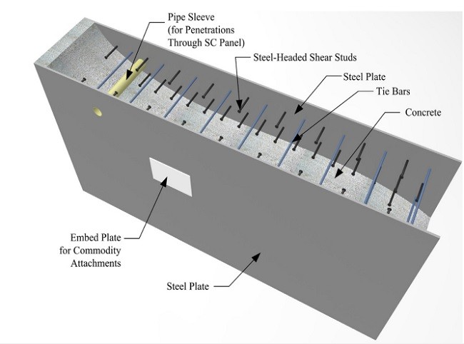
دیوارهای کامپوزیت صفحه فولادی (SC) شامل دو ورق فولادی (سطحی) بیرونی و یک پرکننده بتنی ساده هستند که در شکل 1 نشان داده شده است. ورق های فولادی با استفاده از مهارهای ستونی با نوک فولادی مهارشده اند که این مهارها به سطوح داخلی ورق های فولادی جوش داده شده اند و در بتن قالب گیری می شوند. ورق های فولادی با استفاده از سیستم های اتصال (بست) به یکدیگر متصل می شوند که این سیستم ها نیز در بتن قالب گیری می شوند. عمل آوری کامپوزیت در بین ورق های فولادی و هسته بتنی به وسیله مهارهای ستونی و سیستم های اتصال فراهم می شود. سیستمهای اتصال مزیت های زیر را فراهم می کنند: 1- یکپارچگی ساختاری با دیوار SC با مقاومت در برابر شکاف از طریق هسته بتنی ساده، 2- آرماتور برشی خارج از صفحه، و 3- پایداری در برابر مدول های فولادی خالی در طی حمل ونقل و نصب. مهارهای ستونی نیز شرایط زیر را فراهم می کنند: 1- محدودیت برای کمانش محلی ورق های فولادی، و 2- مقاومت برشی میان پهنه ای.
همان طور که در شکل 1 نشان داده شده است، پرکننده بتنی بین ورق های فولادی محصور می شود. ساخت فروشگاهی مدول های فولادی، شامل ورق های فولادی، سیستم های اتصال و مهارهای ستونی نیز امکان پذیر است، زیرا هیچ گونه تقویت قفسه میله در دیوارهای SC موردنیاز نیست. ورق های فولادی همانند یک آرماتور و چارچوب اولیه برای قالب گیری بتن عمل می کنند و هیچ گونه کار اضافی برای ساخت یا حذف چارچوب نیاز نیست. علاوه براین مزیت ها، سازه های SC در تقریبا نصف زمان موردنیاز برای ساخت سازه های بتن آرمه رایج مشابه ساخته می شوند (شلزمان، 2004). دیوارهای SC اخیرا به عنوان دیوارهای پوسته اولیه و ثانویه در نیروگاه های برق هسته ای (NPP) بکار رفته اند (Mitsubishi Heavy Industries, 2011; Westinghouse Electric Company, 2008).
تحلیل و طراحی تاسیسات هسته ای مربوط به ایمنی شامل دیوارهای SC توسط پیوست N9 of AISC N690s1-15 کنترل می شود (موسسه آمریکایی ساخت فولاد، 2015). این مشخصه بر پایه تحقیقات تجربی و عددی انجام شده توسط این محققان ایجاد شده است: Varma et al. (2014), Zhang et al. (2014), Sener et al. (2015), Sener and Varma (2014), Seo et al. (2015), Bhardwaj et al. (2015) and Bruhl et al. (2015a). برای مثال، طراحی مهارهای ستونی و تاثیر آن بر سطح عملکرد کامپوزیت و کمانش محلی ورق های فولادی در منبع (Zhang et al., 2014) بحث وبررسی شده است. رفتار برشی خارج از صفحه و طراحی دیواره های SC در (Sener and Varma, 2014) و رفتار و طراحی برای خمش خارج از صفحه نیز در (Sener et al., 2015) مورد تجزیه و تحلیل قرار گرفته است. رفتار و طراحی دیوارهای SC برای برش رو به صفحه در (Seo et al., 2015) و رفتار و طراحی دیوارهای SC برای نیروی غشاء ترکیبی عمود بر صفحه و ممان های خارج از صفحه نیز در (Varma et al., 2014) بررسی شده است. همچنین، این استاندارد حداقل الزامات و تدارکات جزئی بخش برای هر جزء (ورق فولادی، مهارهای ستونی، سیستم های اتصال، و پرکننده بتنی) از دیوار SC را فراهم می کند (Bhardwaj et al., 2015).
پیش زمینه
دیوارهای SC در تاسیسات هسته ای مربوط به ایمنی می بایست برای بارگذاری غیرفعال و تحریک کننده طراحی شوند (کمیسیون تنظیم مقررات هسته ای آمریکا). تحقیقات پیشین اثربخشی دیوارهای SC در مقاومت در برابر آسیب محلی (زخمی شدن، نفوذ، سوراخ شدن) ناشی از ضربه موشکی را مطرح کرده اند. میزونو و همکاران (Mizuno et al., 2005) نتیجه گرفتند که یک دیوار SC سطح محافظت یکسانی (به منظور جلوگیری از سوراخ شدن دیوار) را همانند دیوار RC که تقریبا 30% ضخیم تر است، فراهم می کند. برخی از محققان نشان دادند که ورق فولادی را می توان برای فراهم کردن یک ضخامت معادل از بتن درنظر گرفت و کل ضخامت بتن معادل را نیز می توان با معادلات دیوار برای ارزیابی عملکرد ضربه ای بکار برد (Grisaro and Dancygier, 2014; Tsubota et al., 1993; Walter and Wolde-Tinsae, 1984).
نویسندگان اخیرا یک رویکرد سه مرحله ای برای طراحی دیواره های SC جهت جلوگیری از سوراخ شدگی موضعی ناشی از ضربه موشکی ایجاد و تحقیق کرده اند (Bruhl et al. 2015a). این روش را می توان برای محاسبه حداقل ضخامت مورد نیاز ورق فولادی برای جلوگیری از سوراخ موضعی بکاربرد. این روش با استفاده از یک پایگاه داده تجربی جامع از بیش از 100 آزمایش ضربه موشکی تأیید شد. همچنین، نویسنده ها یک طرح توسعه و معیاری از مدل های المان محدود 3 بعدی برای پیش بینی رفتار و شکست محلی دیواره های SC که در معرض ضربه موشکی هستند، ارائه کرده اند (Bruhl et al., 2015a). این مدل ها با استفاده از نتایج حاصل از پایگاه داده تجربی مورد سنجش قرار گرفت و نتایج آن برای تایید مکانیزم شکست دیوارهای SC که در معرض ضربه موشکی هستند، بکار گرفته شد. مدل های سنجش شده برای انجام مطالعات پارامتری تحلیلی جهت گسترش پایگاه داده و تایید بیشتر روش طراحی بکار رفتند. تحقیقات پیشین پاسخ ساختاری یا حداکثر انحراف دیوار SC که در معرض ضربه موشکی قرار دارد، لحاظ نکرده اند. متعاقبا، دیوار SC طراحی شده از سوراخ موضعی جلوگیری می کند اما دیگر معیارهای طراحی مانند حداکثر حدود انحراف را ارضاء نمی سازد.
دیوارهای SC باید طوری طراحی شوند که معیارهای کلی طراحی مانند خمش، برش، چرخش یا حدود انحراف را برآورده سازند. بااین حال، تحقیقات محدودی درباره تاثیر کلی یا رفتار دو طرفه دیوارها یا تاوه های SC وجود دارد. Sohel and Liew (2011, 2014) عملکرد ساختاری (رفتار کلی و محلی) یک پیکربندی خاص از تاوه های SC شامل ورق های فولادی مهارشده به هسته بتن با استفاده از قلاب های J شکل که هم به عنوان مهارهای ستونی و هم سیستم های اتصال عمل می کنند، بررسی کرده اند. این محققان به طور تجربی مقاومت استاتیک تاوه های دو طرفه با تکیه گاه ساده را که در معرض بارگذاری قطعه مرکزی است، ارزیابی کردند (Sohel and Liew, 2011). پارامترهای شامل شده عبارتند از ضخامت هسته بتنی، ضخامت ورق های فولادی، و نوع بتن (سبک وزن یا تقویت شده با فیبر). نویسنده ها نتیجه گرفتند که رفتار تاوه های SC مشابه با رفتار تاوه های RC است. مکانیزم خط تسلیم مشاهده شده و منحنی های بار – انحراف آن مشابه با عملکرد تاوه های RC دو طرفه با تکیه گاه ساده است. مدهای احتمالی شکست شامل شکست برشی پانچ (منگنه ای)، شکست اتصال دهنده برشی، کمانش و تسلیم ورق های فولادی است. هنگامی که مدهای شکست برشی پانچ و شکست اتصال دهنده برشی جلوگیری شد، پاسخ بار– انحراف، خمیری کاملا الاستیک بود، تا این که انحرافات بزرگ و عمل آوری غشاء افزایش لازم در مقاومت را ایجاد کرد. مقادیر شکل پذیری انحراف برای تاوه های SC با وزن معمول و هسته های بتنی سبک وزن، به ترتیب تقریبا برابر با 10 و 15 است.
نتایج حاصل از بررسی تجربی عملکرد ساختاری تاوه های SC با قلاب های J شکل که در معرض بارگذاری ضربه ای هستند، در منبع (Sohel and Liew, 2014) ارائه شده است. پارامترهای آن عبارتند از: ضخامت هسته بتنی، ضخامت ورق فولادی، و نوع بتن (سبک وزن یا تقویت شده با فیبر). تاوه های SC با استفاده از جرم 2700 پوندی با پرتابه نیمه کره ای (رهاشده) از ارتفاع 9.9 ft در معرض ضربه قرار گرفتند که منجر به سرعت های ضربه 22-24 ft/s شد. نتایج تجربی شامل اثر محلی و پروفیل تغییرشکل تاوه های SC در بالا و پایین ورق های فولادی، همراه با اثر زمان – نیرو بود. Sohel and Liew یک روش تعادل انرژی به منظور برآورد حداکثر انحراف و نیروی ضربه توسعه دادند. شکل ایده آل تابع مقاومت استاتیک (بار-انحراف) که در مطالعه قبلی آن ها اندازه گیری شده بود، به عنوان ورودی در محاسبه تعادل انرژی بکار رفت. نتایج تحلیلی حداکثر جابجایی وسط دهانه را تا 22% و نیروی ضربه را تا 25% کمتر برآورد می کند.
abstract
Steel-plate composite (SC) walls consist of a plainconcrete core reinforced withtwo steelfaceplates onthe surfaces. Modules (consisting of steel faceplates, shear connectors and tie-bars) can be shop-fabricated and shipped to the site for erection and concrete casting, which expedites construction schedule and thus economy. SC structures have recently been used in nuclear power plant designs and are being considered for the next generation of small modular reactors. Design for impactive and impulsive loading is an important consideration for SC walls in safety-related nuclear facilities. The authors have previously developed design methods to prevent local failure (perforation) of SC walls due to missile impact. This paper presents the development of static resistance functions for use in single-degree-of-freedom (SDOF) analyses to predict the maximum displacement response of SC walls subjected to missile impact and designed to resist local failure (perforation). The static resistance function for SC walls is developed using results of numerical analyses and parametric studies conducted using benchmarked 3D finite element (FE) models. The influence of various design parameters are discussed and used to develop idealized bilinear resistance functions for SC walls with fixed edges and simply supported edges. Results from dynamic non-linear FE analysis of SC panels subjected to rigid missile impact are compared with the maximum displacements predicted by SDOF analyses using the bilinear resistance function. Published by Elsevier B.V.
1. Introduction
Steel-plate composite (SC) walls consist oftwo exterior (surface) steelfaceplates withplainconcrete infill as showninFig. 1. The steel faceplates are anchored to the concrete core using steel headed stud anchors that are welded to the interior surfaces of the steel faceplates and cast in concrete. The steel faceplates are connected to each other using tie systems that are also cast in concrete. Compos-ite actionbetweenthe steelfaceplates andconcrete core isprovided by the stud anchors and the tie systems. The tie systems provide: (a) structural integrity to the SC wall by resisting splitting through the plain concrete core, (b) out-of-plane shear reinforcement, and (c) stability to the empty steel modules during transportation and erection. The stud anchors provide: (a) restraint for local buckling of steel faceplates, and (b) interfacial shear resistance.
As shown in Fig. 1, the concrete infill is contained between the steel faceplates. Shop fabrication of steel modules, consisting of the steel faceplates, tie systems and stud anchors, is possible because no reinforcing bar cages are required in SC walls. The steel faceplates serve as primary reinforcement and formwork for casting concrete. No additional work is required to construct or remove formwork. Due to these efficiencies, SC structures can be constructed in approximately half the time required for similar conventional reinforced concrete (RC) structures (Schlaseman,SC walls have recently been used as primary and secondary shield walls in nuclear power plants (NPP) (Mitsubishi Heavy Industries, 2011; Westinghouse Electric Company, 2008).
The analysis and design of safety-related nuclear facilities consisting of SC walls is governed by Appendix N9 of AISC N690s1-15 (American Institute of Steel Construction, 2015). This specification is built upon experimental and numerical research conducted by Varma et al. (2014), Zhang et al. (2014), Sener et al. (2015), Sener and Varma (2014), Seo et al. (2015), Bhardwaj et al. (2015) and Bruhl et al. (2015a). For example, the design of stud anchors and its influence on the level of composite action and local buckling of the steel faceplates is discussed in (Zhang et al., 2014). The out-of-plane shear behavior and design of SC walls is discussed in (Sener and Varma, 2014), and the behavior and design for out-of-plane flexure is discussed in (Sener et al., 2015). The behavior and design of SC walls for in-plane shear is discussed in (Seo et al., 2015), and the behavior and design of SC walls for combined in-plane membrane force and out-of-planemoments is discussed in (Varma et al., 2014). The specification also provides minimum requirements and section detailing provisions for each component (steel faceplate, stud anchors, tie systems, and concrete infill) of the SC wall (Bhardwaj et al., 2015).
2. Background SC
walls in safety-related nuclear facilities have to be designed for impactive and impulsive loading (U.S. Nuclear Regulatory Commission, 2001). Previous research has demonstrated the effectiveness of SC walls in resisting local damage (scabbing, penetration and perforation) due to missile impact. Mizuno et al. (Mizuno et al., 2005) concluded that an SC wall provides the same level of protection (preventing wall perforation) as an RC wall that is approximately 30%thicker. Several researchershave suggestedthat the steelfaceplate can be considered to provide an equivalentthickness of concrete, and the total equivalent concrete thickness may be used with RC wall equations to evaluate impact performance (Grisaro and Dancygier, 2014; Tsubota et al., 1993; Walter and Wolde-Tinsae, 1984).
The authors have recently developed and verified a three-step approach for designing SC walls to prevent local perforation due to missile impact(Bruhl et al., 2015a). The method can be used to compute the minimum required steel faceplate thickness to prevent local perforation. The method was verified using a comprehensive experimental database of over 100missile impacttests. The authors also presented the development and benchmarking of 3D finite elementmodels for predicting the behavior and localfailure of SC walls subjected to missile impact(Bruhl et al., 2015a). These models were benchmarked using results from the experimental database, and the results were used to confirm the failure mechanism of SC walls subjected to missile impact. The benchmarked models were used to conduct analytical parametric studies to expand the database, and further verify the design method. This previous research does not consider the structural response or the maximum deflection of the SC wall subjected to missile impact. Consequently,the designed SC wall may prevent local perforation, but not satisfy other design criteria such as maximum deflection limits.
SC walls should also be designed to satisfy global design criteria such as flexure, shear, rotation or deflection limits. However, there is limited literature available on the global impact or twoway behavior of SC walls or slabs. Sohel and Liew (2011, 2014) evaluated the structural performance (local and global behavior) of a unique configuration of SC slabs consisting of steel faceplates anchored to the concrete core using j-hooks serving as both stud anchors and tie systems. They experimentally evaluated the static resistance of simply supported two-way slabs subjected to central patch loading (Sohel and Liew, 2011). The parameters included were the thickness of the concrete core, thickness of the steel faceplates, and the type of concrete (lightweight or fiber reinforced). The authors concluded that the behavior of SC slabs was similar to that of RC slabs. The observed yield line mechanism and load–deflection curves were similar to those of two-way, simply supported, RC slabs. Possible failure modes included punching shear failure, shear connector failure, buckling and yielding of steel faceplates. When punching shear failure and shear connector failure modes were prevented, the load–deflection response was elastic-perfectly plastic until large deflections and membrane action provided additional increase in strength. Deflection ductility values were approximately 10 and 15 for SC slabs with normal weight and lightweight concrete cores, respectively.
Results fromexperimentalinvestigationofthe structuralperformance of SC slabs with j-hooks subjected to impact loading were presented in (Sohel and Liew, 2014). The parameters included were the concrete core thickness, steel faceplate thickness, and type of concrete (lightweight or fiber reinforced). The SC slabs were subjected to impact using a 2700-lb mass with hemispherical projectile head guided (dropped) from a height of 9.9-ft resulting in impact velocities of 22–24 ft/s. The experimental results included the local indentation and the deformation profile of the SC slabs at both the top and bottom steel faceplates, along with the impact force-time history. Sohel and Liew developed an energy balance method to estimate the maximum deflection and impact force. An idealized form of the static resistance (load–deflection) function measured in their previous study (Sohel and Liew, 2011) was used as input in the energy balance calculation. The analytical results underestimated maximum mid-span displacement by up to 22%, and impact force by up to 25%.
چکیده
1. مقدمه
2. پیش زمینه
3. رویکرد
3 – 1. روش SDOF برای پانل های RC
3 – 2. روش SDOF برای پانل های SC
4. مقاومت استاتیک پانل های SC: مدل های عددی و معیار سنجش
4 – 1. مدل عددی: روش المان محدود سه بعدی (FEM)
4 – 2. تحقیق مدل 3D FEM
5. تابع مقاومت استاتیک: مطالعات پارامتریک
5 – 1. رفتار خمشی پانل های SC
2.5. مقاومت استاتیک دوخطی ایدهآل
3.5. تاثیر پارامترها
6. تحلیل SDOF دیوارهای SC
1.6. فاکتور انتقال جرم
2.6. محدودیتها
3.6. مقایسه نتایج تحلیل ضربه
7. خلاصه و نتیجهگیری
Abstract
1. Introduction
2. Background
3. Approach
3.1. SDOF method for RC panels
3.2. SDOF method for SC panels
4. Static resistance of SC panels: numerical models and benchmarking
4.1. Numerical model: 3D finite element method (FEM)
4.2. Verification of 3D FEM model
5. Static resistance function: parametric studies
5.1. Flexural behavior of SC panels
5.2. Idealized bilinear static resistance
5.3. Influence of parameters
6. SDOF analysis of SC walls
6.1. Mass transformation factor
6.2. Limitations
6.3. Comparison of impact analysis results
7. Summary and conclusions
7.1. Future work