
دانلود رایگان مقاله زمینه محاسبات آنتن نوری
میکروسکوپ نوری نزدیک میدان مبتنی بر آنتن و طیفسنجی از زمینه نوری افزایش یافته بهصورت محلی برای ایجاد نزدیکی نانوساختارهای فلزی-لیزر به عنوان prob محلی استفاده میکند. با استفاده از شبیهسازی سه بُعدی بر اساس روش عنصر محدود، به مطالعه میدانهای الکترومغناطیسی نزدیک آنتن مختلف نوری میپردازیم و توپولوژی آن را به منظور استخراج یک بهبود قوی در یک محدوده فرکانس انتخابشده، بهینهسازی میکنیم. نتایج ما دستورالعمل روشنی برای ساخت کارآمد ساختار آنتن و برای بهبود حساسیت طرح میکروسکوپ نزدیک میدان ارائه میکند.
1. معرفی
آنتنها قطعاتی برای دریافت و انتقال امواج الکترومغناطیسی هستند. درحالیکه آنتنها دستگاههای اولیه در برنامههای کاربردی فرکانس رادیویی برای مدت طولانی هستند، مفهوم آنتن نوری نسبتاً جدید است. بهطور یکسان، آنتنهای نوری اجزای طراحی شده برای انتقال سیگنالهای بهینهی نوری هستند. محدودهی کاربرد سیگنال جایی است که در آن آنتن نوری بهاحتمال زیاد به عنوان امواج رادیویی مورد استفاده قرار میگیرد. پیش از این یک منطقه کاربردی ایجاد شده برای آنتن نوری، میکروسکوپ نوری نزدیک میدان و طیفسنجی است. بنابراین آنتن بهطور موثر انرژی یک موج الکترومغناطیسی را به انرژی موضعی تبدیل میکند. مفهوم آنتن نه تنها برای افزایش قدرت سیگنال و حل دوبارهی آن استفاده شده است بلکه برای نفوذ نرخ واپاشی تابشمولکولها نیز استفاده شده است. در مرور اجمالی میکروسکوپ نوری نزدیک میدان (SNOM)، آنتنهای نوری اغلب شامل نوک برش فلز هستند، که توسط یک پرتو لیزی مشخص میشوند. نوک به انرژی پرتو لیزر ورودی متمرکز شده است درحالیکه نور به یک منطقه بسیار موضعی که ابعاد آن اساساً توسط هوشیاری از نوک (در حال حاضر پایین تر از 10 نانومتر) تعریف شده است تمرکز دارد. سپس اثرات فیزیکی چند برابر میشود و اغلب تعیین آن سخت است: اثرات ثابت مانند اثر رعدوبرق و همچنین اثرات پویا مانند سطح پلاسمون پلاریتون (SPP). برای مثال، با توجه به اثر رعدوبرق، هر هندسه تیز باید به عملکرد بالایی در الکتریسیته دست یابد، اما در عمل تنها نیمی از راهنماییها افزایش خوب میدان الکتریکی را نشان میدهد حتی اگر آنها به همان اندازه تند باشند. بهعلاوه، افزایش زمینه بستگی به محیط محلی، در شکل نوک و همچنین در آزمایش (شرایط نور) دارد. اخیراً تنها آزمایشهای فلورسانس مولکول این چالشها را نشان دادهاند: راهنماییهای طلایی برای افزایش فلورسانس ضعیف به دلیل اثر غالب رفع فلورسانس در فواصل کوتاه یافت شده است. یک آنتن نوری خوب قادر به افزایش یک میدان محلی قوی و انرژی پراکندگی پایین است. اخیراً، آنتن نوری خوب برای کاربردهای فلورسانس توسط ذرات کلوئیدی طلا متصل به الیاف شیشه ارائهشده است. اما محلیسازی و توان افزایش زمینه در حد متوسط است. Anger و همکارانش وابستگی کل فلورسانس را در بررسی فاصلهی مولکول اندازهگیری کردند. همانگونه که مولکول فاصله کاهش مییابد، ابتدا نرخ فلورسانس با توجه به افزایش تأثیر زمینه افزایش مییابد و پس از آن، در فواصل کوچکتر از 5 نانومتر، قطرهها به دلیل انرژی غیرتابشی به ذره انتقال مییابند. برای بهبود افزایش میدان، spheroids یا Nanorods میتواند استفاده شود. همانگونه که بعدا نشان خواهیم داد، nanorod مانند آنتن دو قطبی شناخته شده از تئوری آنتن کلاسیک عمل میکند. بااینحال، در فرکانسهای نوری، خواص فلزات تفاوت قابل توجهی با رفتار آنها در امواج رادیو یا مایکرو پیدا میکند. علاوه بر تشخیص با واکنشهای آنی به حرکت میدان خارجی الکترونها در فلز مانند یک پلاسما محدود توسط توپولوژی خاصی رفتار میکند. در نتیجه، رزونانس یک آنتن نوری ساخته شده از فلزات واقعی، انتقال سریع با توجه به تشدید یک فلز کامل دارد. Muhlschlegal و همکارانش تشدید طلا دو قطبی در آنتنها را مورد بررسی قرار دادهاند. طول آنتن در رزونانس به گونه چشمگیری کمتر از نیمی از تحریک طول موج است. میدان قوی را میتوان در فاصله آنتن دو قطبی یافت. ساختار آنتن مشابه آنتن bow-tie است، که اخیراً توسط Schuck همکارانش مورد مطالعه قرار گرفته است. لبههای تیز منجر به نور بهتر در مرکز ساختار میشود. ساختار مشابه با یک لیزر دیود تجاری توسط Cubukcu و همکارانش یکپارچه شده است. اگرچه برای SNOM یک آنتن مورد نیاز است، که در آن حداکثر میدان الکتریکی در راس یک پروب نوری واقع شده باشد. با استفاده از این محدودیت، استراتژیهای مختلف برای رسیدن به یک میدان قوی محلی را بررسی میکنیم. همهی شبیهسازیها و نتایج ارائهشده در این مقاله با استفاده از COMSOL چند فیزیکی، یک ابزار بر اساس روش المان محدود (FEM)، انجام شده است.
2. نانو ذرات طلا
به دلیل توپولوژی سادهی آن، یک ذره فلز یک نمونه آنت ساده است. راهحل تحلیل شناخته شده است و مقایسه کمی با دادهها مستقیماً تجربی است. پراکندگی نور توسط یک دی الکتریک برای اولین بار توسط Mie تحلیل شد. برای ذرات کوچک (در حد شبه استاتیک)، در توزیع میدان خارجی برق را میتوان با میدانهای دو قطبی واقع در مرکز توصیف کرد. میدان الکتریکی کل میتواند به عنوان یک برهمنهی میدان حاصل و میدان پراکنده با استفاده از تخمین دو قطبی باشد. که در آن ε پیچیدگی مجاز است. برای تمام محاسبات ε از Johnson و Christy گرفته شده است. به دلیل وجود یک راهحل تحلیلی برای این مشکل، سیستم کاملاً برای اعتبار عددی روش مورد استفاده در این مطالعه مناسب است. بنابراین درمییابیم که نتایج عددی FEM در شرایط تقریباً کامل با راهحل تحلیلی (1) است و از این رو کد FEM میتواند با قابلیت اعتماد به ساختار آنتن پیچیدهتر اعمال شود. برای تحریک طول موج برابر با 650 نانومتر حداکثر شدت افزایش در سطح کره 12.5 است.
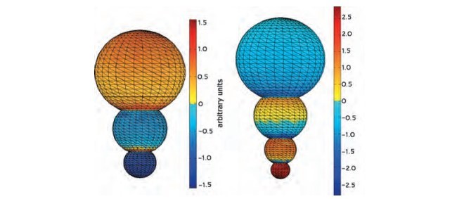
در مرحله بعد کرهی دومی را در فاصلهی اولین متغیر معرفی کردیم. در مقایسه با افزایش میدان یک کره تک، پیشرفت بسیار قوی در فاصله بین دو حوزه ایجاد شده است. علاوه براین، تغییرات رزونانس متمایل به سرخ است. ما هردو حوزه را جدای از هم بررسی کردیم. همانگونه که در شکل 1 نشان دادهشده است یک تفاوت مهم بین این دو مورد وجود دارد: یک دو قطبی در ساختارهای متصل وجود دارد، درحالیکه در مورد دوم، یک دو قطبی در هر کره وجود دارد. دو قطبی القا شده از دو حوزهی جدا از هم باهم تعامل میکنند و چون نشانههای مختلف در سطح نزدیکترین حوزه وجود دارد تراکم بار متقابل سطح بالا است. بازده ازدحام خطوط میدان الکتریکی بین دو حوزه بالاست و از این رو افزایش میدان در فاصله نزدیک حوزهها بسیار قوی میشود.
برای موارد دیگر از دو کرهی به هم پیوسته یک دوقطبی در کل ساختار القا میشود. در نتیجه طول موج رزونانس در مقایسه با دو مورد بسیار طولانی است. جالب توجه است که، یک یکتایی در توزیع میدان الکتریکی را میتوان در لبههای دندانهدار یافت، که منجر به یک ناپیوستگی چگالی بار سطحی میشود و از این رو میدان بسیار بالا است. با انتخاب اندازه میدان مختلف، عدم تقارن را میتوان معرفی کرد و جابجایی توزیع میدان الکتریکی به سمت میدانهای کوچکتر پدیدار میشود. اگر نسبت بالایی از شعاع منجر به پیشرفت میدان الکتریکی به دو انتهای کره شود، حداکثر شدت میدان تمایل به اختلاف اندازه بین افزایش میدان دارد. فاصله همپوشانی تحت تأثیر میدان الکتریکی کل قرار میگیرد. با تغییر شعاع و فاصله همپوشانی، طول کل تغییر مییابد و از این رو تغییرات طول موج رزونانس رنگ آبی متمایل میشود. اگرچه طول موج رزونانس نیز بستگی به پارامترهای دیگر، مانند شعاع کره و همپوشانی از راه دور دارد.
Antenna-based near-field optical microscopy and spectroscopy makes use of locally enhanced optical fields created near laser-irradiated metal nanostructures acting as local probes. Using threedimensional simulations based on the finite element method we study the electromagnetic fields near various optical antennas and we optimize their geometry in order to bring out a strong enhancement in a selected frequency range. Our results provide clear guidelines for the fabrication of efficient antenna structures and for improving the sensitivity of current near-field microscopy schemes.
1.INTRODUCTION
Antennas are components to receive and transmit electromagnetic waves.Whereas antennas are primary devices in radio frequency applications for many years, the concept of optical antennas is relatively new.Analogously, optical antennas are components designed to transceive optical signals.The application range where optical antennas will be used is likely to become as wide as the one for the radio wave counterpart.Already an established application area for optical antennas is near-field optical microscopy and spectroscopy.1 There the antenna efficiently converts the energy of an incident electromagnetic wave to highly localized energy.The antenna concept is used to increase the signal strength and the resolution but also to influence the radiative decay rates of sample molecules.In scanning near-field optical microscopy (SNOM), the optical antenna often consists of a sharp noble metal tip, which is illuminated by a laser beam.The tip localizes the energy of the incoming laser beam such that light is concentrated to a highly localized area whose dimensions are essentially defined by the sharpness of the tip (currently down to 10 nm).The underlying physical effects are manifold and often hard to determine: static effects such as the lightning rod effect as well as dynamic effects such as surface plasmon polariton (SPP) resonances contribute to the antenna behavior.For example, according to the lightning rod effect, any sharp geometry should yield high electrical fields, but in practice only about half of the tips show a good electrical field enhancement even if they are equally sharp.Additionally, the field enhancement depends on the local environment, on the tip shape and also on the experiment itself (illumination conditions).Recent single molecule fluorescence experiments are very indicative for these challenges:2 etched gold tips were found to provide weak fluorescence enhancement because of the predominating effect of fluorescence quenching at short distances. A good optical antenna has to provide a strong local field enhancement and low energy dissipation.Currently, good optical antennas for fluorescence applications are provided by colloidal gold particles attached to the end of an etched glass fiber tip.But the field localization and the magnitude of the field enhancement are modest.Anger et al.2 have measured the total fluorescence dependence on the probe– molecule distance.As the distance is reduced, the fluorescence rate first increases due to the field enhancement effect and then, at distances smaller than ∼5 nm, drops because of nonradiative energy transfer to the particle.To improve the field enhancement, spheroids or nanorods can be used.As shown later, a nanorod behaves like a downscaled dipole antenna known from classical antenna theory. However, at optical frequencies the properties of metals are significantly different from their behavior at radiowave or microwave frequencies.Rather than being characterized by an instantaneous response to the driving external field the electrons in the metal behave like a plasma confined by the particular geometry of the metal’s boundaries.Consequently, the resonances of an optical antenna made of real metals are red-shifted with respect to the resonances of a perfect metal.Mühlschlegel et al.3 have investigated the resonance of gold dipole antennas.The antenna length at resonance has been found to be considerably shorter than one-half of the excitation wavelength.The strongest field can be found in the feed gap of the dipole antenna.A similar antenna structure is the bow-tie antenna, which has been recently studied by Schuck et al.4 The sharp edges lead to an even better confinement of the light in the center of the structure.The same structure has been integrated on the facet of a commercial diode laser by Cubukcu et al.5 for the purpose of a plasmonic laser antenna.However, for SNOM an antenna is needed, where the maximum electrical field is located at the apex of an optical probe. Using this constraint, we investigate different strategies to achieve a strong local field enhancement.All the simulations and results presented in this article have been performed using COMSOL multiphysics, a software toolkit based on the finite element method (FEM).
2.GOLD NANOPARTICLES
Because of its simple geometry a metal particle is a simple prototype antenna.Analytical solutions are known and quantitative comparisons with experimental data are straightforward.The scattering of light by a dielectric sphere has first been solved analytically by Mie.6 For small particles (in the quasi-static limit), the external electrical field distribution can be described by the fields of a dipole located at the center of the sphere.7 The total electric field can be given as a superposition of the incident field and the scattered field using the dipole approximation. where ε is the complex permittivity.For all calculations ε has been taken from Johnson and Christy.9 Because of the existence of an analytical solution for this problem, the system is perfectly suitable for a validation of the numerical approach used in this study.We find that the numerical FEM results are in nearly perfect agreement with the analytical solution (1) and hence the FEM code can be reliably applied to more complex antenna structures.For an excitation wavelength of nm = 650 nm the maximum intensity enhancement at the surface of the sphere is found to be ∼12.5.
In a next step we have introduced a second sphere at variable distance to the first one.Compared to the field enhancement of a single sphere, much stronger enhancements are found in the gap between the two spheres. Furthermore, the resonance shifts to the red.We have investigated both separated and intersecting spheres.As shown by the charge distributions in Figure 1 there is an important difference between these two cases: a single dipole is induced in the connected structures, whereas in the latter case, a dipole is induced in each individual sphere.The induced dipoles of the two separated spheres interact and because the charges are of different sign on the surfaces of closest proximity the spheres experience a mutual attractive force.The high surface charge density yields to crowding of electrical field lines between the two spheres and hence the field enhancement of closely spaced spheres becomes very strong.
For the other case of two interconnected spheres only a single dipole is induced over the whole structure.A consequence thereof is a much longer resonance wavelength compared to the case of two separate spheres.10 Interestingly, a singularity in the electrical field distribution can be found at the edges of the indent, which leads to a discontinuity of the surface charge density and hence to extremely high fields.By choosing spheres of different sizes an asymmetry can be introduced giving rise to a displacement of the electric field distribution towards the smaller sphere (c.f.Fig.1).Although a high ratio of the radii leads to a high ratio of electrical field enhancements at the two sphere ends, the maximum field intensity tends to decrease as the size difference between the spheres increases.The overlap distance also influences the total electrical field enhancement.We have found the highest field strengths for an overlap distance of 1.4 nm. By varying the radii and the overlap distance, the total length changes and hence the resonance wavelength shifts to the blue.However, the resonance wavelength also depends on other parameters, such as the sphere radii and the overlap distance.
1. معرفی
2. نانو ذرات طلا
3. آنتن خود مشابه
4. گویهای حفاظت شده توسط پوشش طلایی Silver
5. Nanorod
6. نتیجهگیری
منابع
1.INTRODUCTION
2.GOLD NANOPARTICLES
3.SELF-SIMILAR ANTENNA
4.SILVER SPHERES PROTECTED BY A GOLD COATING
5.NANORODS
6.CONCLUSIONS
References