
دانلود رایگان مقاله استراتژی کنترل دی کوپلینگ توان بهبود یافته بر اساس ژنراتور سنکرون مجازی
چکیده
طرح کنترل ژنراتور سنکرون مجازی (VSG) که میتواند بعنوان یک ضمیمه از کنترل دروپ در نظر گرفته شود، توجه محققان را بخاطر اضافه کردن لختی دورانی به اینروترها بخود جلب کرده است. این مقاله در مورد یک تکنیک دیکوپلینگ اکتیو و راکتیو برای VSGها در ریز شبکه، بعنوان یک جنبه مهم از VSG بحث میکند. مکانیزم سنتی دیکوپلینگ توان در ابتدا تحلیل میشود. متعاقباً، خواص امپدانس خط در درجات ولتاژ مختلف مقایسه میشوند. نتایج نشان میدهند که روش دیکوپلینگ توان سنتی برای ریزشبکههای با ولتاژ متوسط و پایین مناسب نیست. در نتیجه، یک روش دیکوپلینگ با توان افزایش یافته پیشنهاد میشود. با تخمین ولتاژ در نقطه کوپلینگ مشترک و ردیابی مقادیر مرجع آنها، توان اکتیو و راکتیو خروجیِ اینورترها میتواند دیکوپلینگ دینامیک را انجام دهد. علاوهبراین، پایداری ساختار کنترل جدید و انتخاب ضرایب مرتبط تحلیل میشوند. نتایج شبیهسازی و آزمایشی، استراتژی دیکوپلینگ بهبود یافته را برای VSGها تأیید میکنند.
1. مقدمه
تولید پراکنده، بعنوان فرم اصلی تولید توان انرژی تجدیدپذیر، نقش مهمی در حل بحران انرژی فعلی و مسائل زیست محیطی ایفا میکند. برای ارتقای تعامل منبع توان پراکنده، بعضی محققان ریزشبکهها را پیشنهاد دادهاند [1]. یک ریزشبکه، یک ساختار شبکه جدید است که از تعدادی ژنراتور پراکنده، دستگاههای ذخیرهسازی انرژی، دستگاههای تبدیل انرژی، بارها و دستگاههای محافظت تشکیل میشود. ریزشبکهها میتوانند بطور انعطافپذیر کنترل خودکار، محافظت خودکار و مدیریت خودکار را اجرا کنند. آنها همچنین میتوانند تأثیر تعداد زیادی از منابع توان پراکنده که به شبکه دستیابی دارند را بوسیلهی فعلوانفعال متقابل با مکمل شبکه کاهش دهند. بااینوجود، در مقایسه با ژنراتورهای سنکرون (SGs) در یک سیستم توان تودهای، اینورتر الکترونیکی توانِ یک ریزشبکه ناهمگونی قابل توجهی را روی ویژگیهای خارجی نشان میدهد، از جمله امپدانس خارجی و ظرفیت پایینتر. علاوهبراین، اینورتر ریزشبکه بخاطر عدم وجود لختی سیستم، قابلیت ضد اختلال ضعیفی را نشان میدهد. تمام این نواقص ناپایداری سیستم توان را بدتر خواهند کرد [2، 3].
تا به امروز، کنترل دروپ پر استفادهترین روش کنترل در ریزشبکهها است. یک اینورتر ریزشبکه، بوسیله ردیابی سیگنالهای ولتاژ مرجع تولید شده بوسیلهی کنترل کننده دروپ، توان اکتیو و راکتیو را بطور منطقی تخصیص میدهد. این روش مشابه با اشتراکگذاری توان بین SGهای موازی است و آن به ژنراتورها اجازه میدهد تا یک قابلیت اتصال و اجرا را بدست آورند و بدون خط ارتباطی متصل شوند. بااینوجود، چندین نقص هنوز در فرایند اجرای آن وجود دارد. بخاطر عدم وجود لختی دورانی، اینورتر با کنترل دروپ نمیتواند پشتیبانی فرکانس ضروری و میرایی به یک سیستم توان را فراهم کند. برای اضافه کردن مکانیزم "همگامسازی" SGها به اینورترها، تعدادی از محققان یک کنترل جدید به نام ژنراتور سنکرون مجازی (VSG) را پیشنهاد کردهاند که به اینورترها امکان میرا کردن نوسانات توان را بوسیلهی شبیهسازی معادلات حرکت روتور میدهد و در نتیجه پایداری سیستم را افزایش میدهد. VSG مزایای SGها و اینورترها ادغام میکند؛ در نتیجه این راهحل جدید برای اینورترها از زمان پیشنهاد شدنش بطور وسیعی بررسی شده است [4-11].
بهینهسازیهای مختلف برای VSG بر اساس ملزومات مختلف ارائه شدهاند. VSG در واقع از مکانیزم کنترل دیکوپلینگ توان مشابه مانند موردِ کنترل دروپ در فرایند اجرای آن استفاده میکنند؛ این مکانیزم شامل یک حلقه کنترل اشتراکگذاری توان اکتیو (P-f) و یک حلقه کنترل اشتراکگذاری توان راکتیو (Q-V) است [12]. امپدانس خط در یک ریزشبکه بطور کلی مقاومت یا خاصیت مقاومت-اندوکتانس را نشان میدهد؛ در نتیجه، یک کوپلینگ قوی وجود بین کنترل توان اکتیو و راکتیو دارد، و چنین کوپلینگی ممکن است روی پایداری و عملکرد دینامیک سیستم توان تأثیر بگذارد [13]. محققان استراتژیهای دیکوپلینگ توان بسیاری را برای کنترل دروپ پیشنهاد کردهاند که میتوانند به سه دسته تقسیم شوند. یک روش دیکوپلینگ مستقیم بر اساس آرایه بهره نسبی پیشنهاد شده در [14، 15] است. در این روش، یک ماتریس تبدیل توان با امپدانس سیستم ساخته میشود و یک کانال کنترل بهتر بوسیلهی تخمین رابطه کوپلینگ بین توان و ولتاژ انتخاب میشود. بااینوجود، این طرح ممکن است به یک استراتژی ولتاژ-توان اکتیو (P-V) و فرکانس-توان راکتیو (Q-f) در یک محیط خط مقاومتی تبدیل شود که با SGهای سیستمهای توان موجود ناسازگار است. در این بین، آن برای فراهم کردن امکان دیکوپلینگ توان هنوز به یک القاگر مجازی نیاز دارد. روش دوم، روش دیکوپلینگ توان مجازی بر اساس تبدیل مختصات پیشنهاد شده در [12، 16، 17] است. از طریق اضافه کردن یک ماتریس دوران مختصات متشکل از زاویه امپدانس خط، جریانهای توان حقیقی میتوانند به جریانهای توان مجازی دیکوپل شده تبدیل شوند. اگرچه روش پیشنهاد شده در [17] میتواند اشتراکگذاری توان واقعی را تضمین کند اگر زوایای امپدانس خط پراکنده هر DG متفاوت باشند، این روش میتواند فقط از یک انحراف بزرگ از هدف کنترل جلوگیری کند و نمیتواند دیکوپلینگ کامل را بدست آورد. روش سوم، کنترل دیکوپلینگ مبتنی بر امپدانس مجازی پیشنهاد شده در [18-21] است. در این روش، یک حلقه امپدانس مجازی بوسیلهی تفریق کردن افت ولتاژ آن در سمت خروجی حلقه ولتاژ اجرا میشود و امپدانس سیستم طوری اصلاح میشود که القایی باشد. بااینوجود، یک القاگر مجازی بالا در یک محیط خط مقاومتی لازم است و ممکن است افت ولتاژ باس را بدتر کند. علاوهبراین، تعیین مقدار امپدانس واقعی با در نظر گرفتن عملکرد دینامیک و پایداری سیستم دشوار است. در [21]، یک مقاومت منفی مجازی برای خنثی کردن تأثیر مقاومت خط استفاده شد که در نتیجه یک امپدانس سیستم عمدتاً القایی را تضمین میکند. تأثیر پارامترهای حاصل روی پایداری سیستم تحلیل میشود. بااینوجود، در این مقاله یک واحد اصلاح کننده برای بدست آوردن تأثیر دیکوپلینگ مطلوب معرفی میشود؛ در نتیجه، پیچیدگی سیستم افزایش مییابد.
در این مقاله، یک روش دیکوپلینگ توان جدید برای VSG بر اساس ولتاژ در نقطه برآورد کننده کوپلینگ مشترک (VPCC) پیشنهاد شده است. از طریق ردیابی مقدار مرجع VPCC، امپدانس سیستم میتواند برای برآورده کردن دیکوپلینگ توان لازم اصلاح شود. متفاوت با روش امپدانس مجازی سنتی، تأثیر امپدانس خط روی توان خروجی، بجای تضعیف شدن بوسیلهی اعمال طرح پیشنهاد شده، میتواند کاملاً حذف شود. در این بین، پایداری ساختار کنترل جدید و انتخاب ضریب اصلاح بررسی میشوند.
بقیه مطالب این مقاله به ترتیب زیر ارائه میشوند. مدل الگوریتم VSG در بخش 2 معرفی میشود. توان-فرکانس و کنترل کننده تحریک بترتیب بوسیلهی روش تحلیل سیگنال کوچک ساخته میشوند. در بخش 3 مکانیزم کوپلینگ توان بررسی میشود و روش دیکوپلینگ توان متداول معرفی میشود. متعاقباً، روش دیکوپلینگ معرفی شده بر اساس برآورد کننده VPCC در بخش 4 بطور کامل تحلیل میشود. در نهایت، شبیهسازی و نتایج آزمایشی بدست میآیند.
2. استراتژی کنترل VSG
2.1. ساختار مدار اصلی
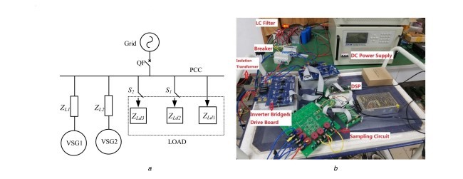
ساختار توپولوژی مدار اصلی بر اساس الگوریتم کنترل VSG در شکل 1 قسمت a نشان داده شده است. یک منبع جریان مستقیم (DC) بجای منبع توان پراکنده برای ساده کردن تحلیل استفاده میشود.
مدار اصلی سیستم از یک منبع DC، یک اینورتر منبع ولتاژ سه فاز و شبکه ایدهآل تشکیل میشود. بر اساس ساختار ریزشبکه، بعضی از بارهای اکتیو و راکتیو بطور کلی به نقطه کوپلینگ مشترک (PCC) متصل میشوند. Rg و Lg امپدانسهای خط هستند؛ RL، L و C بترتیب مقاومت، القاگر فیلتر و خازن فیلتر LC هستند؛ uo و io بترتیب ولتاژ و جریان خروجی اینورتر هستند؛ ic جریان خازن است. توانهای خروجی بوسیلهی نمونهبرداری uo و io بدست میآیند. آنها برای تولید سیگنال مرجع ولتاژ در کنترل کننده VSG استفاده میشوند. مشابه با اکثر روشهای کنترل DG، حلقه ولتاژ از کنترل کننده شبه-PR برای تضمین کردن دقت ردیابی استفاده میکند.
Abstract
Virtual synchronous generator (VSG) control scheme, which can be regarded as an extension of droop control, has received much attention from researchers as the introduction of rotational inertia to inverters. This study discusses an active and reactive power decoupling technique for VSGs in microgrid, as an important aspect of VSG. The traditional power decoupling mechanism is initially analysed. Subsequently, the properties of the line impedance at different voltage degrees are compared. Results indicate that the traditional power decoupling method is unsuitable for medium- and low-voltage microgrids. Thus, an improved power decoupling method is proposed. By estimating the voltage at the point of common coupling and tracking their reference values, the output active and reactive power of inverters can perform dynamic decoupling. Furthermore, the stability of the new control structure and selection of relevant coefficients are analysed. The simulation and experimental results verify the enhanced decoupling strategy for VSGs.
1 Introduction
Distributed generation, as the main form of renewable energy power generation, plays an important role in solving the current energy crisis and environmental problems. To promote the integration of distributed power supply, some scholars have proposed microgrids [1]. A microgrid is new network structure comprising numbers of distributed generators, energy storage devices, energy conversion devices, loads and protection devices. Microgrids can flexibly implement self-control, self-protection and self-management. They can also alleviate the effect of a large number of distributed power supply accessing the grid by interacting with the grid supplement. However, compared with the synchronous generators (SGs) in a bulk power system, the power electronic inverter of a microgrid presents significant distinction on outer features, including lower capacity and output impedance. Moreover, the inverter of microgrid exhibits poor anti-disturbance capability because of the lack of system inertia. All these drawbacks will exacerbate the instability of the power system [2, 3].
To date, droop control is the most frequently used control method in microgrids. A microgrid inverter allocates active and reactive power reasonably by tracking the reference voltage signals generated by the droop controller. This method is similar to the power sharing between parallel SGs and it allows the distributed generators to realise a plug-and-play function and interconnect without communication line. However, some drawbacks are still present in its implementation process. Lacking rotational inertia, the inverter with droop control cannot provide the necessary frequency support and damping to a power system. To introduce the ‘sync’ mechanism of SGs to inverters, some scholars have proposed a new control named virtual synchronous generator (VSG), which enables inverters to damp power oscillations by simulating rotor motion equations and consequently enhance the stability of the system. VSG integrates the advantages of both SGs and inverters; thus, this new solution for inverters has been widely studied since its proposal [4–11].
Various optimisations for VSG have been presented according to different requirements. VSG actually uses the same power decoupling control mechanism as that of the droop control in its implementation process; this mechanism consists of an active power sharing control loop (P–f) and a reactive power sharing control loop (Q–V) [12]. The line impedance in a microgrid generally presents resistive or resistance-inductance property; Consequently, a strong coupling exists between the control of active and reactive power, and such coupling may influence the stability and dynamic performance of the power system [13]. Scholars have proposed many power decoupling strategies for droop control, which can be divided into three categories. A direct decoupling method based on relative gain array is proposed in [14, 15]. In this method, a power transformation matrix with the system impedance is constructed and a better control channel is selected by estimating the coupling relationship between power and voltage. Nevertheless, this scheme may become a voltage–active power (P– V) and frequency–reactive power (Q–f) droop strategy in a resistive line environment, which is incompatible with SGs of the existing power systems. Meanwhile, it still requires a virtual inductor to enable power decoupling. Second, virtual power decoupling method based on coordinate transformation is proposed in [12, 16, 17]. Through introducing a coordinate rotation matrix composed by the impedance angle of line, real power flows can be transformed into decoupled virtual power flows. Although the method proposed in [17] can guarantee the sharing of actual power if the distributed line impedance angles of each DG are different, this method can only avoid a large deviation from the control objective and it cannot realise complete decoupling. Third, the virtual impedancebased decoupling control is proposed in [18–21]. In this method, a virtual impedance loop is implemented by subtracting its voltage drop on the input side of the voltage loop and the impedance of system is modified to be inductive. However, a high virtual inductor is required in a resistive line environment and may aggravate the bus voltage drop. Furthermore, the value of virtual impedance is difficult to determine considering the dynamic performance and stability of the system. In [21], a virtual negative resistor is used to counteract the effect of the line resistance thus ensuring a mainly inductive system impedance. The influence of the resulting parameters on system stability is analysed. However, a correcting unit is introduced in this paper to obtain the desired decoupling effect; as a result, the complexity of the system is increased.
In this article, a new power decoupling method for VSG is proposed based on voltage at the point of common coupling (VPCC) estimator. Through tracking the reference value of VPCC, the system impedance can be modified to meet the power decoupling requirement. Different from traditional virtual impedance method, the impact of line impedance on output power can be eliminated completely rather than be weakened by applying the proposed scheme. Meanwhile, the stability of new control structure and selection of correlation coefficient are studied.
The rest of this paper is organised as follows. The VSG algorithm model is established in Section 2. Power–frequency and excitation controller are constructed by small signal analysis method, respectively. The mechanism of power coupling is studied and the conventional power decoupling method is introduced in Section 3. Subsequently, the proposed decoupling method based on VPCC estimator is fully analysed in Section 4. Finally, simulation and experimental results are obtained.
2 Control strategy of the VSG
2.1 Structure of main circuit
The topology structure of the main circuit based on the VSG control algorithm is shown in Fig. 1a. A direct current (DC) source is used to instead of distributed power supply to simplify analysis.
The main circuit of the system consists of a DC source, a threephase voltage source inverter and ideal grid. According to the microgrid structure, some active and reactive loads are generally connected to the point of common coupling (PCC). Rg and Lg are line impedances; RL, L and C are the resistance, filter inductor and capacitor of the LC filter, respectively; uo and io are the output voltage and current of the inverter, respectively; ic is the current of capacitor. The output powers are obtained by sampling uo and io . They are used to generate the voltage reference signal in the VSG controller. Similar to most DG control methods, the voltage loop adopts quasi-PR controller to ensure tracking precision.
چکیده
1. مقدمه
2. استراتژی کنترل VSG
2.1. ساختار مدار اصلی
2.2. کنترل کننده توان-فرکانس
2.3. ساختار کنترل کننده تحریک
2.4. حلقه داخلی کنترل ولتاژ
3. تحلیل کوپلینگ توان
4. طرح دیکوپلینگ توان برای VSG
4.1. توان اکتیو و کنترل مستقل فرکانس
4.2. توان راکتیو و کنترل دیکوپلینگ ولتاژ
4.3. تحلیل پایداری و انتخاب پارامتر
4.4. انتخاب ضریب دروپ
5. تحلیل آزمایشی و شبیهسازی
5.1. تحلیل شبیهسازی
5.1.1. عملکرد کنترل VSG
5.1.2. اعتبارسنجی روش دیکوپلینگ توان پیشنهاد شده
6. نتیجهگیری
منابع
Abstract
1. Introduction
2 .Control strategy of the VSG
2.1 Structure of main circuit
2.2 Power–frequency controller
2.3 Structure of the excitation controller
2.4 Voltage control inner loop
3 .Power coupling analysis
4 .Power decoupling scheme for VSG
4.1 Active power and frequency independent control
4.2 Reactive power and voltage decoupling control
4.3 Stability analysis and parameter selection
4.4 Selection of droop coefficient
5 .Simulation and experimental analysis
5.1 Simulation analysis
5.1.1 Performance of the VSG control
5.1.2 Verification of proposed power decoupling method
6 .Conclusion
References