
دانلود رایگان مقاله تست ارتعاشی قاب های تقویت شده فولادی با میراکننده های برشی
چکیده
یک مطالعه جدول لرزه ای از مدل تک فاصله دو طبقه از قاب تقویت شده هم مرکز مرسوم (OCBF) و قاب تقویت شده با رابط برشی آلومینیوم (SLBF)، برای ارزیابی بازدهی رابط برشی به عنوان وسیله اتلاف انرژی انجام شد. مدل های کاهشی مقیاس 1:12 برای حرکت زمینی تفت (Taft) از شتاب های افزایشی اوج زمین به کار گرفته شد، که بارهای زلزله ای با شدت افزایشی را نشان می دهد. قوانین تشابه برای مدلسازی مناسب رفتار دینامیک مدل های کاهشی تشخیص داده شد و مقادیر زمان ، فرکانس و شتاب مقیاس بندی شد. تست نشان داد که قاب SLBF در حدود 41-64 % کمتر از برش پایه را در مقایسه با OCBF برای سطوح PGA متغیر حرکات زمین جذب کرد. روش مشابه برای ممان- های واژگونی و شتاب کف ملاحظه شد. به هرحال، رانش های کف طبقه اول برای SLBF همواره بیشتر از OCBF بود. مقدار زیادی از انرژی به وسیله بارگذاری اتصال برشی آلومینیوم، برای رضایتبخشی پاسخ به مقیاس PGA با 1.7g حرکت تفت اتلاف شد، در حالی که قاب OCBF نتوانست مقیاس PGA با 0.8g را نجات دهد. اثبات تست های مفهومی به تایید اعتبار روش طراحی ارائه شده برای توزین قاب های فولادی با رابط برشی آلومینیوم، نیز کمک کرد.
1. معرفی
تحت شرایط زمین لرزه، اعتماد به سالم ماندن ساختار پایه ثابت، به توانایی آن برای اتلاف انرژی زلزله بستگی دارد، که زمانی که دستخوش تغییرشکل های غیرالاستیک به ویژه در نواحی ریز تیرها و ستون ها بر اساس سیستم های بار گرانشی می شود، اتفاق می افتد. با استفاده از وسایل اتلاف انرژی (EDDs) ، که به راحتی قابل جایگزین شدن هستند، این امکان وجود دارد که از جمع شدن تغییرشکل های غیرالاستیک در اعضای مقاومتی بار گرانشی اصلی و استقرار صدمه القایی جلوگیری کنیم. تابع اساسی EDDs این است که بخشی از انرژی ورودی را کاهش یا جذب نماییم، و بدین وسیله صدمه اتلاف انرژی روی اعضای ساختاری اصلی را کاهش داده و صدمه ساختاری ممکن را به کمترین مقدار برسانیم.
یک استراتژی شایع برای اتلاف انرژی در ساختار حین زلزله، درخلال تغییرشکل غیرالاستیک وسایل فلزی می باشد [1-3]. خمیدگی تسلیم میراکننده های فولادی مانند TADAS, ADAS ، با استفاده از صفحات فولادی با اشکال مثلثی توسعه داده شد تا پتانسیل اتلاف انرژی ماکسیمم شود[4 - 6]. نشان داده شده است که جان تیر درزدار و بسته نیز در برش و عمل بعنوان میراکننده تحت بارهای متعاقب، تسلیم می شوند [7-9]. چند مطالعه دیگر روی صفحات برشی فولادی با تسلیم کم نیز انجام شده است که تغییرشکل برشی آن را به عنوان وسیله ای برای اتلاف انرژی بهینه می کند [10].
تسلیم برشی فلزات آلیاژی با تسلیم کم، مانند آلومینیوم، بسیار نرم است و تغییرشکل های غیرالاستیک بزرگ بدون پارگی یا کمانش ممکن است. تسلیم در حالت برشی سهم ماده در تغییرشکل پلاستیک بدون کرنش محلی بیش ازحد را ماکزیمم می کند. در این خصوص، اتصالات I شکل با آلیاژهای آلومینیوم با تسلیم کم، وسایل اتلاف انرژی عالی محدود کننده ساختار شناخته شده اند [11 - 13]. به علاوه، اضافه کردن اتصالات برشی آلومینیوم به یک قاب تقویت شده یراق معمولی (OCBF) ، همانطور که در شکل 1 نشان داده شده است بطور قابل ملاحظه ای بازدهی ارتعاشی آن را افزایش می دهد. مطالعه تحلیلی نشان دادکه اضافه کردن اتصالات برشی، باعث کاهش قابل ملاحظه در برش پایه که عمل کننده بعنوان میراکننده به وسیله اتلاف مقدار زیادی از انرژی زلزله القائی در ساختار است، خواهد شد. تعدادی از تست های اعضاء روی اتصالات برشی کاهشی و تمام مقیاس، بازدهی خوبی در گستره ای فرکانس ها را نشان می دهد[11و14]. به هرحال، هیچ تست سیستمی به وسیله ثابت قراردادن اتصال برشی داخل یک قاب فولادی انجام نشده است که تاثیرگذاری قاب های تقویت شده اتصال برشی (SLBFs) را نشان دهد.
تست های شبیه سازی زمین لرزه مرجع کم ارزشی از اطلاعات برای فهمیدن رفتار سیستم های ساختاری در گستره غیرخطی می باشند. تست های جدول لرزه برای ارزیابی مکانیزم مقاومت بار، الگوی شکست/صدمه و رفتار پسماند سیستم های اتصال برشی، و برای فراهم کردن داده رویه طراحی توسعه مناسب در توزیع عناصر مختلف سیستم کلی، به کار گرفته شد.
هدف اصلی این تلاش تحقیقی، مطالعه بازدهی SLBF ، با طراحی براساس روش پیشرفته رای و والاس [11] با استفاده از آزمایشات جدولی است. یک مقیاس مدل کاهشی 1 : 12 براساس دقت روابط تشابه و تست های شبیه سازی زلزله هدایت شد. بازدهی SLBF براساس شتاب های کف، برش های پایه، ممان های واژگونی و پاسخ پسماند اتصالات برشی ارزیابی شد. به طور مشابه، مدل با جزییات مشابه مدل SLBF به منظور مقایسه بازدهی با SLBF تست شد.
2. اتصال برشی آلومینیوم به عنوان میراگر زلزله
اتصال برشی معمولی با دو صفحه در شکل 1 نشان داده شده است که از صفحات نازک شکل دهنده بال ها، جان تیر و سفت کننده هایش ساخته شده است. اتصال برشی آلومینیوم برای تسلیم در حالت برشی برای محدودکردن نیروی متعاقب ماکزیمم طراحی شده است، که به ساختار اصلی منتقل شده است و برای فراهم کردن پتانسیل کافی اتلاف انرژی طی لرزش زمین، به وسیله تغییرشکل غیرالاستیک در وسیله میراگر است. به علاوه، مقدار کافی از کرنش نسبی آلیاژهای آلومینیوم به اتصالات برشی اجازه می دهد تا در برابر بارهای متعاقب اضاقی پس از تسلیم اولیه مقاومت کند و به اتصالات برشی طبقه های دیگر نیرو وارد کند تا بار را در ساختار چند طبقه ای تقسیم کند. در نتیجه، فعالیت های غیرالاستیک درطول یراق ها و طبقه های ساختمان پخش می شود. این خصوصیات ، اتصال برشی آلومینیوم را برای هردوی ساختمان های جدید و بهبود ساختارهای موجود جذاب می کند. اتصالات آلومینیوم به صورت استراتژیک برای تسلیم در برش باید در ساختار جایگذاری شوند؛ برای مثال، در قاب های تقویت شده معمولی بین گره های قطری و تیر کف، همانطور که در شکل 1 نشان داده شده است، جای داده شده است[11].
3. تست شبیه سازی زلزله
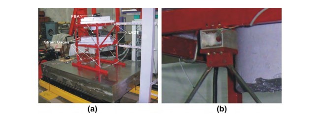
3.1. ساختمان مدل
یک ساختمان دو طبقه در محدوده زمین لرزه V (PGA = 0.36g) در نوع پروفایل خاک I (سنگ، یا خاک سخت) با IS 1893 (بخش 1) برای آنالیز مفروض است[15]. در نقشه، ساختمان در جهت شرق به غرب 36 متر طول (شش رابط 6 متری) و 18 متر عرض در جهت شمال به جنوب (3 رابط 6 متری) دارد، همانطور که در شکل 2 نشان داده شده است. در ارتفاع، فاصله بین طبقات 5 . 4 متر است و ساختمان هیچ گونه بی نظمی ندارد. در جهت شمال-جنوب ، شش سیستم قاب شمع زنی برای فراهم کردن مقاومت متعاقب سطح کد طراحی شده است. بار مرده و زنده ساختمان به ترتیب در سقف و کف 3.8 kPa و 3 kPa مفروض است. 6 سیستم قاب شمع زنی در رابط میانی در جهت شمال جنوب به صورت سیستم SLBF و سایر قاب های داخلی برای مقاومت در برابر تنها نیروهای گرانش مربوط با ناحیه های انشعابی طراحی شده اند.
رویه طراحی ظرفیت در توزین مولفه های سیستم SLBF پیروی می شود که برای ظرفیت میراکننده ها به طوری که قاب قبل از اینکه به تنش برشی شکست نرسد تسلیم نشود، طراحی شده اند. فلسفه طراحی مشابه برای چنین وسیله های اتلاف انرژی تسلیم، استفاده شده است[16و17]. رابط های برشی برپایه دو حالت محدود مطالبه استحکام و قابلیت کشش سطح طراحی و زلزله های معتبر ماکزیمم، طراحی شده اند. اندازه رابط برشی با محاسبه ناحیه افقی جان تیر موردنیاز برای مقاومت برش طراحی طبقه مشابه OCBF محاسبه می شود. کرنش برشی طراحی γd = δ /d مربوط به رانش مجاز طبقه است، δ در سطح زلزله طراحی (معمولا 4. 0 درصد ارتفاع طبقه) و عمق d رابط برشی بین 10/1 و 12/1 ارتفاع طبقه انتخاب می شود.
Abstract
A shake table study of single-bay two-storey model of conventional ordinary concentric braced frame (OCBF) and aluminum shear-link enabled braced frame (SLBF) was conducted to evaluate the performance of shear-link as energy dissipation device. The 1:12 reduced scale models were subjected to Taft ground motion of increasing peak ground accelerations, representing seismic loads of increasing severity. Similitude laws for adequate modeling of dynamic behavior of the reduced models were satisfied and time, frequency and acceleration values were scaled. The test indicated that SLBF frame attracted about 41–64% less base shear compared to OCBF for varying PGA levels of the ground motions. Similar trend was noticed for overturning moments and floor acceleration as well. However, the first storey floor drifts for the SLBF were always greater than the OCBF. Significant amount of energy was absorbed by aluminum shear-links leading to satisfactory response up to the scaled PGA of 1.7g of the Taft motion, while the OCBF frame could not survive the scaled PGA of 0.8g. These proof-of-concept tests also helped validate the design methodology developed for proportioning aluminum shear-link enabled steel frames.
1. Introduction
Under seismic action, reliance for survival of fixed-base structure is placed on its ability to dissipate seismic energy, which occurs while undergoing large inelastic deformations in specially detailed regions of beams and column bases of the gravity load system. With the use of energy dissipation devices (EDDs), which can be easily replaced, it is possible to prevent accumulation of inelastic deformation in the main gravity load resisting members and localization of the damage induced. The basic function of EDDs is to reduce and/or absorb a portion of the input energy, and thereby reducing the energy dissipation demand on primary structural members and minimizing possible structural damage.
A widely considered strategy for the dissipation of energy in the structure during an earthquake is through the inelastic deformation of metallic devices [1–3]. Flexure yielding of steel dampers such as TADAS, ADAS were developed using steel plates of triangular shapes to maximize energy dissipation potential [4–6]. Solid and slit webs of steel section has also shown to yield in shear and act as a damper under lateral loads [7–9]. A few studies have also been carried out on low yielding steel shear panels utilizing its shear deformation as a means to dissipate the energy [10].
The shear yielding of low yielding alloy metals, such as aluminum, has been found to be very ductile and large inelastic deformations are possible without tearing or buckling. The yielding in shear mode maximizes the material participating in plastic deformation without excessive localized strains. In this regard I-shaped shear-links of low yield ductile alloys of Aluminum have been found to be excellent energy dissipative devices limiting the energy dissipation demand on structural members of the primary structure [11–13]. Further, the addition of aluminum shear-links to an ordinary chevron braced frame (OCBF) as shown in Fig. 1 has shown to improve its seismic performance remarkably. The analytical study indicated that addition of shear-links leads to considerable reductions in the base shear which acted as dampers by dissipating significant amount of seismic energy induced in the structure. A number of element tests on the reduced and full-scale shear-links showed satisfactory performance over a wide range of frequencies [11,14]. However, no system test by means of fixing the shear-link within a steel frame has been conducted to verify the effectiveness of shear-link braced frames (SLBFs).
Earthquake simulation tests are an invaluable source of information for understanding the behavior of the structural systems in the nonlinear range. Shaking table tests were conducted to evaluate the load resistance mechanism, failure/damage pattern and the hysteretic behavior of shear-link systems and to provide the data for developing suitable design procedures for proportioning various elements of the overall system.
The primary objective of this research effort is to study the performance of the SLBF, designed as per the simplified method developed by Rai and Wallace [11], using shake table experiments. A 1:12 reduced scale model was fabricated with due care of dynamic similitude relations and earthquake simulation tests were conducted. The performance of the SLBF was evaluated in terms of floor accelerations, base shears, overturning moments, and hysteretic response of shear-links. Similarly, OCBF model having same details as that of SLBF model was tested in order to compare the performance with the SLBF.
2. Aluminum shear link as seismic damper
Typical shear-link with two panels is shown in Fig. 1, which is fabricated from thin plates forming its flanges, web and stiffeners. The aluminum shear-link is designed to yield in shear mode to limit the maximum lateral force, which is transmitted to the primary structure, and to provide significant energy dissipation potential during the earthquake ground shaking by means of inelastic deformation in the damping device. In addition, significant amount of strain hardening of aluminum alloys allows the shear-links to resist additional lateral loads after the first yield and thus forcing shear-links of other stories to share the load in a multi-storied structure. Consequently, the inelastic activities are spread out across various bays and stories of the building structure. These properties make the aluminum shear-link attractive for both new buildings and improvement to existing structures. Aluminum links should be placed strategically in the structure to yield in shear; for example, in ordinary chevron braced frames it is placed in between the diagonal braces and the floor beam as shown in Fig. 1 [11].
3. Earthquake simulator testing
3.1. Prototype building
A two-storey community building assumed to be located in seismic zone V (PGA = 0.36g) on the soil profile Type I (Rock, or hard soil) of IS 1893(Part 1) [15] was considered for analysis. In the plan, the building is 36 m long in the E–W direction (six bays @ 6 m) and 18 m (three bays @ 6 m) wide in the N–S direction as shown in Fig. 2. In the elevation, floor to floor heights are 4.5 m and the building is assumed to possess no irregularity of any kind. In the N–S direction, six bracing frame system were designed to provide the code level lateral resistance. The building was assumed to have a dead load and live load of 3.8 kPa and 3 kPa, respectively, on roof and floor. The six bracing frame systems at the middle bay in N–S direction are designed as SLBF systems and all the other interior frames were designed to resist only gravity loads associated with their tributary areas.
The capacity design approach is followed in proportioning various components of the SLBF system. They are designed for the capacity of the dampers such that the frame does not yield before the dampers reach their failure shear stress. Similar design philosophy has been used for such yielding energy dissipation devices [16,17]. The shear-links are designed based on two limit states of strength and ductility demands of the design level and maximum credible earthquakes. Size of shear link is calculated by determining the horizontal web area required to resist the design storey shear taken same as that of OCBF. The design shear strain, cd = d/ d corresponds to the allowable storey drift, d at design level earthquake (typically 0.4% of storey height) and the depth d, of shear-link is chosen between 1/10th and 1/12th of storey height. The peak shear stress and strain values in the shear-links follow a power law relation given by smax ¼ 2:6 r0:2c0:2 where r0.2 is the tensile yield strength of web material [11].
چکیده
1. معرفی
2. اتصال برشی آلومینیوم به عنوان میراگر زلزله
3. تست شبیه سازی زلزله
3.1. ساختمان مدل
3.2. مدل
3.3. مدار تست
3.4. پیشینه بارگذاری و شبیه سازی زلزله
4. مشخصات دینامیکی
4.1. تست لرزش آزاد
4.2. تست لرزش اجباری
5. سنجش نتایج تست زلزله
5.1. رفتار کلی و مکانیزم شکست
5.2. پاسخ شتاب
5.3. برش پایه و ممان های واژگونی
5.4. رانش های کف
6. خلاصه و نتایج
منابع
Abstract
1. Introduction
2. Aluminum shear link as seismic damper
3. Earthquake simulator testing
3.1. Prototype building
3.2. Model
3.3. Test set-up
3.4. Loading history and earthquake simulation
4. Dynamic characteristics
4.1. Free vibration test
4.2. Forced vibration test
5. Evaluation of earthquake test results
5.1. Overall behavior and failure mechanism
5.2. Acceleration response
5.3. Base shear and overturning moments
5.4. Floor drifts
6. Summary and conclusions
References