
دانلود رایگان مقاله طراحی و بررسی تجربی کاهش ارتعاش سازه خرپای میرای مرکب فضایی
چکیده
به منظور حل و فصل مشکل نقص ابزار فوتوالکتریکی در هنگام بزرگ بودن زیاد پاسخ ارتعاش سازه مرکب (مرکب) خرپا، از روش بکارگیری لایه میرایی مقید ویسکوالاستیک روی دیواره خرپا و پانل جعبه ای برای کاهش ارتعاش کل ساختار بهره گرفته می شود. در این مقاله یک لوله طویل شکسته با لایه میرایی مقید ویسکوالاستیک معرفی می گردد. لوله طویل ساختار اصلی به دو لوله کوتاه همسان شکسته می شود و یک لوله دارای لایه میرایی آزاد به محل اتصال دو لوله کوتاه اضافه می گردد که توسط لوله طویل چسبنده و شکسته متصل می شود. با تحلیل پاسخ فرکانس خرپای فضای سنتی و سازه بار هوافضا و سازه لوله طویل شکسته، نمودار ابری پاسخ شتاب و منحنی پاسخ شتاب گره ثابت اندازه گیری بدست می آید. آزمایشاتی به منظور تعیین و بررسی امکان اجرای سازه انجام شد. نتایج آزمایش نشان می دهد که روش لوله بلند شکسته با لایه میرایی مقید ویسکوالاستیک می تواند تأثیر میرایی بهتری از سازه خرپای سنتی در پی داشته باشد و سطح ارتعاش بار فضایی موجود در انتهای خرپا را به طور موثر کاهش داده و مرجع مهمی برای طراحی کاهش ارتعاش سایر سازه های فضایی باشد.
مقدمه
با توسعه فضاپیما از لحاظ بزرگی و پیچیدگی، خرپای فضایی به دلیل پیاده کردن راحت آن، تکنولوژی مناسب، وزن مد و قابلیت تنظیم سازه بر اساس نیازهای خاص کاربرد آن بیش از پیش شده است. علاوه بر این، به عنوان بخش مهمی از ایستگاه فضایی بین المللی نیز محسوب می شود ( به شکل 1 مراجعه کنید). خرپای فضاکار عمدتا از دو جهت مورد استفاده قرار می گیرد. یک برای اتصال تجهیزات اپتوالکترونیک مربوطه در بالای خرپای فضاکار جهت جدا سازی تجهیزات الکترونیک به گونه ای که انترفرنس یا تداخل بین یکدیگر کاهش یابد. دیگری به عنوان سازه پشتیبان جهت پشتیبانی از آنتن های بزرگ کش بستی در پانل های فضاکار و خورشیدی روی ماهواره ها.
خرپای فضاکار و بار آن به کمک حامل پرتاب به کار انداخته می شود. محیط ارتعاش آزمایش شده توسط حامل پرتاب عمدتا به محیط ارتعاش تصادفی یا رندوم و محیط ارتعاش با فرکانس پایین تقسیم بندی می شود. ارتعاش تصادفی عمدتا در اثر صدای اگزوز موتور در طی تیک آف، صدای ایرودینامیک در بخش فراصوتی هواپیما و نوسان فشار در محفظه احتراق موتور می باشد. ارتعاش سینوسی با فرکانس پایین عمدتا ناشی از ارتعاش پوگو، استارت موتور، قطع احتراق و جداسازی درون مرحله ای سازه پروژکتیل یا پرتابه می باشد. نوسان آزاد مودال کم اثر ناشی از احتراق ناقص موتور می باشد. نوع محیط ارتعاش کم فرکانس باعث می شود که سازه خرپای فضاکار دچار آسیب شود، اتصال از بین رود، قطعات سازه کج و معوج شوند و عملکرد کاهش یابد. در عین حال، این ارتعاش باعث دقت ابزارهای فوتوالکتریک کاهش یابد، فرسودگی مکانیکی، کوته مداری و مدار باز فورا و همچنین قصور عملکردی حاصل شود. از اینرو، مطالعه ویژگی های ارتعاش و توقف ارتعاش خرپای فضاکار و بار ان الزامی است. مطالعات متعددی در خصوص کاهش ارتعاش سازه های خرپای فضاکار در دست است که این سازه ها عمدتا به دو دسته تقسیم می شوند: میراگر و لایه میرایی. در مطالعات گذشته، دامپرها یا میراگرها براساس سازه خرپای فضاکار طراحی شدند و رابطه بین موقعیت قرارگیری میراگر و تأثیر کنترل میرایی بررسی شد. YM Park و دیگران یک روش کنترلی نیمه فعال با استفاده از دامپرهای اصطکاک خشک جه کاهش ارتعاش ناپایدار سازه خرپای فضاکار پیشنهاد دادند. J Yang و همکاران ویژگی های میرایی و ارتعاش پانل سندویچی خرپای هرمی شکا مرکب الیاف کربن هیبرید واقع در لایه ویسکوالاستیکی موجود در یک پانل را بررسی کردند. تأثیر میرایی لایه میراکننده با شبیه سازی و آزمایش تجزیه و تحلیل شد. C Liu براساس روس انرژی کرنش مودال (MSE) به تجزیه و تحلیل فرکانس بنیادی ارتعاش، ضریب اتلاف و پیک پاسخ رزونانس سازه خرپای مرکب با لایه های مختلف میرایی پرداخت. تأثیر پارامترهای سازه ای . پارامترهای متریالی لایه میرایی بر تأثیر میرایی خرپای مرکب مطالعه گردید. در خرپای فضاکار سنتی، لایه میرایی به صورت مستقیم روی لوله طویل اعمال می شود و تأثیر میرایی به دلیل لوله طویل و سختی زیاد، مناسب نیست. در این مقاله، سازه خرپای سنتی با کمک یک لایه میرایی آزاد روی اتصال لوله کوتاه چندقسمتی ارتقا داده می شود و تیوب رشد توسط لوله کوتاه و چسبنده متصل می شود. لایه میرایی ویسکوالاستیک برای خرپای فضاکار و سازه بار فضاکار جهت کاهش ارتعاش و مطابق با نیازهای واقعی بکار برده می شود. به کمک شبیه سازی و مقایسه آزمایشی، سازه مرکب جدید از لحاظ وزنی مد تر، دارای سختی کمتر و از نظر تأثیر میرایی بهتر است. چنین سیستم کاملی از ارتعاش دوطرفه آزمایشات شبیه سازی دارای اهمیت هدایتی مثبت برای کاربرئ لایه میرایی ویسکوالاستیک در میدان هوا و فضا می باشد.
تئوری بنیادی مواد میرایی ویسکوالاستیک
چنانچه ماده الاستیک در معرض نیروی خارجی قرار گیرد، کرنش و تنش همزمان افزایش و کاهش میابد، فاز دو اساس یکی است و رابطّ تنش-کرنش به صورت یک خط مستقیم است. ماده میرایی ویسکوالاستیک پس از اعمال نیروی خارجی با ماده الاستیک فرق دارد. کرنش پس از تنش با تأخیر مواجه می شود و زاویه فاز پسماند مغناطیسی طبق شکل2(a) ، α است. رابطه تنش-کرنش یک منحنی طبق شکل 2(b) نشان می دهد.
طراحی خرپا و سازه بار
برای مدلسازی سازه خرپای فضاکار و بار فضاکار طبق اشکال 3 و 4، کل سازه از دو لوله طویل و قبل و بعد از لوله کوتاه ، بالا و پایین آن دارای پوشش طرفین چپ و راست با فلز روکش شده، قطعات انسدادی اتصالی، چفت و بست، پیچ استاندارد به وزن 15.848 kg و ماده AL7075 ساخته شده است.
سازه جعبه بار فضاکار متشکل از یک سازه شبیه ورقه فلزی با سازه سوراخی درون آن می باشد و از یک پیچ برای اتصال سطوح مختلف استفاده نمی شود. علاوه بر هشت وجه سازه جعبه سازه، مرکز سایر سطوح دارای یک شیار مدور به ضخامت 18mm و عمق 2 mm می باشد. این مرکز برای اتصال قطعات، اتصال لوله طویل، لوله کوتاه و اتصال بلوک از طریق اتصال قطعه استفاده می شود.
برقراری مدل اِلمان محدود
مدل المان محدود با سیستم مختصات دست راست انطباق دارد: o اصلی در خط مرکز صفحه سرپوش پایینی موازی با جهت طول بار فضاکار قرار دارد. جهت سرپوش سمت چپ به سمت سرپوش راست و محور y به موازات جهت عرض بار فضاکار جهت سرپوش جلو به سمت سرپوش عقب در جهت مثبت محور Z می باشد.
با انتخاب سیستم بین المللی واحدها، مش بر کل بخش اتوماتیک به صورت دستی تقسیم می شود، المان های مش سه ضلعی و المان های چهارضلعی و بلوک های اتصالی و رابط ها طبق شکل 5 به مش حجم تفکیک می شود.
سایر قسمت ها به مش های پوسته ای تقسیم می شوند و مدل المان در شکل 6 نشان داده شده است. تعداد واحدها 162,717 و وزن مدل 15.23 kg می باشد.
یک سازه لوله طویل شکسته نشان داده می شود. همانطور که در شکل 7 نشان داده می شود، لوله طویل سازه اصلی به دو لوله کوتاه همسان شکسته می شود و یک لوله AL7075 با طول 50mm و قطر خارجی 12mm و ضخامت دیواره 2mm در محل اتصال دو لوله کوتاه افزوده می شود. یک لایه میرای آزاد با ضخامت 2.5mm روی آن اعمال می گردد که توسط لوله چسبنده و طویل شکسته متصل می شود.
Abstract
In order to solve the problem that the photoelectric instrument may fail when the vibration response of the truss composite structure is too large, the method of applying the viscoelastic-constrained damping layer on the truss wall and the box panel is used to reduce the vibration of the whole structure. In this article, a broken long tube with viscoelasticconstrained damping layer is introduced. The long tube of the original structure is broken into two identical short tubes, and a tube with free damping layer is added to the junction of the two short pipes, which is connected by adhesive and broken long pipe. By analyzing the frequency response of the traditional space truss and spaceflight load structure, and a broken long tube structure, the acceleration response cloud diagram and the acceleration response curve of the fixed measuring node are obtained. Experiments were carried out to verify the feasibility of the structure. The test results show that the method of broken long pipe with viscoelastic-constrained damping layer can achieve better damping effect than the traditional truss structure, and it can effectively reduce the vibration level of the space load at the end of the truss, and has important reference significant for the vibration reduction design of other space structures.
Introduction
With the development of spacecraft toward the direction of large scale and complexity, the space truss has been applied more and more widely because of its easy disassembly, good technology, light weight, and the ability to adjust the structure according to the specific needs. It is also an important part of the International Space Station as shown in Figure 1. The space truss is mainly used in two aspects. One is to connect the related optoelectronic equipment at the top of the space truss to separate the electronic equipment so as to reduce the interference between each other. The other is as a supporting structure to support large deployable antennas in space and solar panels on satellites.
The space truss and its load are launched through the launch vehicle. The vibration environment experienced by the launch vehicle is mainly divided into random vibration environment and low-frequency sinusoidal vibration environment.1 Random vibration is mainly caused by engine exhaust noise during take-- off, aerodynamic noise in transonic flight section, and pressure pulsation in the combustion chamber of the engine. The low-frequency sinusoidal vibration is mainly caused by the pogo vibration, engine start, flameout, and interstage separation of the projectile structure; the low-order modal free oscillation is caused by the gust and the shock wave oscillation in the transonic flight segment; and low-order longitudinal oscillation is caused by incomplete combustion of the engine. This kind of low-frequency vibration environment will cause the space truss structure to be damaged, the connection will be loose, the structural parts will be deformed, and the performance will be decreased. At the same time, this vibration will cause the precision of the photoelectric instruments to be reduced, mechanical fatigue, short circuit, and open circuit instantly, as well as functional failure.2 Therefore, it is necessary to study the vibration characteristics and vibration suppression of space truss and its load.3 There are many literatures on the vibration reduction of space truss structures, which are mainly divided into two categories: damper and damping layer. In previous works,4–6 dampers were designed according to the structure of the space truss, and the relationship between the placement position of the damper and the damping control effect was studied. YM Park et al.7 proposed a semi-active control method using dry friction dampers to reduce the transient vibration of the space truss structure. J Yang et al. studied the vibration and damping properties of a hybrid carbon fiber composite pyramidal truss sandwich panel embedded in a viscoelastic layer in a panel. The damping effect of the damping layer is analyzed by simulation and experiment.8 Based on the modal strain energy (MSE) method, C Liu analyzed the vibration fundamental frequency, loss factor, and resonance response peak of the composite truss structure with different damping layers. The influence of structural parameters and material parameters of damping layer on the damping effect of composite truss was studied.9 In the traditional space truss, the damping layer is directly applied to the long pipe,10 and the damping effect is not good due to the long pipe and the large stiffness. In this article, the traditional truss structure is improved, with a free damping layer on the connection of multisection short pipe, and the growth tube is connected by adhesive and short pipe. The viscoelastic damping layer is applied to the space truss and space load structure for vibration reduction according to actual needs. Through simulation and experimental comparison, the new composite structure is lighter in weight, less rigid, and better in damping effect. Such a complete system of mutual verification of simulation tests has a positive guiding significance for the application of viscoelastic damping layer in aerospace field.
Basic theory of viscoelastic damping materials
When elastic material is subjected to external force,11 the stress and strain increase or decrease at the same time, the phase of the two is basically the same, and the stress–strain relationship is a straight line. The viscoelastic damping material is different from the elastic material,12 after the external force is applied. The strain lags behind the stress, and the hysteresis phase angle is a, as shown in Figure 2(a). The stress–strain relation shows a curve,13 as shown in Figure 2(b).
Design of truss and load structure
For space truss structure modeling and space load, as shown in Figures 3 and 4, the whole structure is made up of long tube, before and after the short tube, cover up and down, left and right sides cover plate, plate, connecting block many parts, fixtures and fittings, standard screw, weighs 15.848 kg, and the material for AL7075.
The structure of the space load box is made of a plate-like structure, with a hollow structure inside, and a screw is used to connect the various surfaces. In addition to the eight faces of the structure of the box structure, the center of the other surfaces has a circular groove with a diameter of 18 mm and a depth of 2 mm. It is used for connecting pieces, connecting the long pipe, short pipe, and connecting block through the connecting piece.
The establishment of finite element model
The finite element model adopts the right-hand coordinate system: the origin o is located at the center line of the lower cover plate along the space load length direction, the left cover plate points to the right cover plate and the y axis along the space load width direction, and the front cover plate points to the back cover plate in the positive direction of z axis.
By choosing the international system of units, the mesh is divided by the whole automatic part manually, the mesh elements are triangular and quadrilateral elements, and the connecting blocks and connectors are partitioned by volume mesh, as shown in Figure 5.
The other parts are divided into shell meshes, and the finite element model is shown in Figure 6. The number of units is 338,564, the number of nodes is 162,717, and the weight of the model is 15.23 kg.
A broken long tube structure is introduced. As shown in Figure 7, the long tube of the original structure is broken into two identical short tubes, and a AL7075 tube with a length of 50 mm, an outer diameter of 12 mm, and a wall thickness of 2 mm is added at the junction of the two short tubes. A free damping layer with thickness of 2.5 mm is applied to it, which is connected by adhesive and broken long pipe.
مقدمه
تئوری بنیادی مواد میرایی ویسکوالاستیک
1. روش MSE
2. روش مقادیر ویژه پیچیده (CEM)
طراحی خرپا و سازه بار
برقراری مدل اِلمان محدود
آزمایش مودال
همبستگی مودال
تحلیل پاسخ فرکانس سازه بار فضاکار و خرپای فضاکار
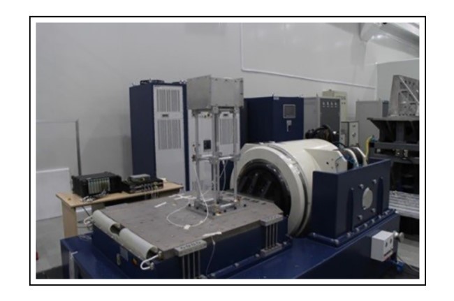
آزمایش ارتعاش خرپای فضاکار
نتیجه گیری
Abstract
Introduction
Basic theory of viscoelastic damping materials
1. MSE method
2. Complex eigenvalue method (CEM)
Design of truss and load structure
The establishment of finite element model
The modal test
Frequency response analysis of space truss and space load structure
Vibration test of space truss
Conclusion
References