
دانلود رایگان مقاله آرایه آنتن دو بانده دایروی قطبی پچ-مثلثی متساوی الاضلاع
مقدمه
آژانش کاوش هوا فضای ژاپن (JAXA) یک ماهواره ثابت به نام VIII (ETS-VIII) ماهواره آزمون مهندسی را در سال 2006 پرتاب نمود. ETS-VIII آزمایشات مسیر چرخش را روی ارتباطات ماهوراه سیار در گستره فرکانسی باند S هدایت خواهد نمود. عمدتاً در حمایت از توسعه فناوری برای انتقال و دریافت اطلاعات چند رسانه ای مانند صوت و تصاویر برای سیستم های سیار زمینی. در این تحقیق، یک آنتن ارایه پچ مثلثی ردیابی-ماهواره دو باندی با مشخصات پایین پیشنهاد شده است. شکل 1 جهت ETS-VIII دیده شده در ژاپن را نشان می دهد که توسط زاویه ارتفاع (El) نشان داده شده که El پرتوی انتن توسعه یافته باید از 38 درجه (شهر Wakanaki در جزیره Hokkaido) تا 58 درجه (شهر Naha در جزیره Okinawa) را برای نگهداری خدمات چند رسانه ای در تمام ژاپن پوشش دهد. بهره مینیمم هدف یافته آنتن در 5dBic در زاویه ارتفاع مرکزی (El=48 درجه) در ناحیه Tokyo برای کاربردهای انتقال داده های حول و حوش 100 کیلوبایت بر ثانیه تنظیم شود. این آنتن باید به صورت نازک،فشرده، کوچک و ساده در حد ممکن برای میسر ساختن گنجاندن در سقف ماشین طراحی شود.
اهداف و مشخصات
جدول I نشاندهنده مشخصات و اهداف مطلوب از یک آنتن برای استفاده با ارتباطات ماهواره سیار، در کابردهای خاص ETS-VIII هدف یافته است که در این تحقیق استفاده می شوند. در این تحقیق، فرکانس عملیاتی برای یک پچ تک در دریافت (Rx) و انتقال (Tx) در 2.5025 گیگاهرتز و 2.6575 گیگاهرتز به ترتیب تنظیم می شوند، همانطور که در جدول I نشان داده شده است. Rx و Tx برای کار در قطبیت دایروی سمت چپ (LHCP) در نظر گرفته می شوند که در آن ماکزیمم نسبت محوری در جهت هدف یافته 3 dB است (زاویه افقی Az=0 تا 360 درجه و El=48).
پیکربندی آنتن
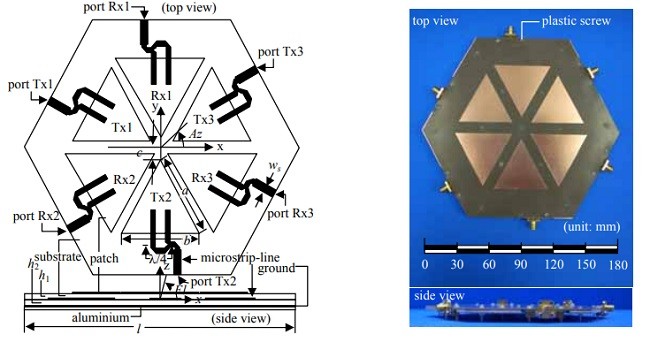
این آنتن به صورت پچ تک قبل از در نظر گرفتن پیکربندی آرایه بررسی می شود. شکل 2، پیکربندی یک پچ مثلثی متساوی الاضلاع تک را با پارامترهای آن نشان می دهد (نفوذپذیری نسبی 2.17 و tan =0.00085). این عناصر با نوع جدید تغذیه های مجاورت با خطوط مایکرواستریپ تغذیه می شود که عرض آن w 3 میلی متر برای هر پچ Rx و Tx برای به دست اوردن پیکربندی نازک است. یک نوع تغذیه دوگانه جدید برای تولد پلاریزاسیون دایروی سمت چپ (LHCP) با استفاده از پچ مثلثی متساوی الاضلاع پیشنهاد می شود که در آن یکی از تغذیه های خط مایکرواستریپ λ/4 طویل تر از دیگر عرضه تاخیر فازی 90 درجه است. تکنیک تغذیه پیشنهاد شده برای دستیابی به توزیع جریان پایدار و ایده ال در سطح پچ مثلثی و در نتیجه بهبود انتن توسعه یافته قبلی طراحی شده است [1] در این تحقیق، روش لحظه ای (MOM) برای شبیه سازی مدل با صفحه زمین متناهی به کار گرفته شد. ضخامت زیرلایه برای خط مایکرواستریپ یا خط تغذیه ( زیرلایه 2) و پچ مثلثی (زیرلایه 1) با مورد ضمنی دیگر (h1=h2=0.8 میلی متر) تعریف می شود. طول های خط مایکرواستریپ درج شده تحت چپ le 14 میلی متر و 10 میلی متر برای Rx و Tx به ترتیب می باشند و مبدل ربع موج برای دستیابی به تطبیق امپدانس 50 اهم برای Rx و Tx به ترتیب استفاده می شود. پارامترهای جزئی خط مایکرواستریپ (شکل 2 را ببینید) برای Rx و Tx ls=5mm ld=11 mm, ld1=4 mm, lc=5 mm, lm= 2 mm, and lst=11 mm است.
عرض خط ورودی مایکرواستریپ ws برای Rx و Tx 4.7 میلی متر و 4 میلی متر به ترتیب است. پارامترهای طول پچ (برای a=b) به دست آمده 52.5 میلی متر و 49.4 میلی متر برای Rx و Tx به ترتیب می باشد. شکل 3 نشاندهنده پیکربندی آنتن ارایه پچ مثلثی است؛ مقطع های Tx و Rx از سه عنصر مثلثی تشکیل شده اند. این پیکربندی برای مینیمم نمودن کاربرد فضایی استفاده می شود. انتن ارایه پچ مثلثی ساخته شده رد شکل 4 از سمت بالا و جانبی نشان داده شده است. یک صفحه الومینیوم با ضخامت 2 میلی متر برای حمایت زیرلایه استفاده می شود.
عملکرد آنتن
شکل 5 پارامترهای S به دست آمده از مدل شبیه سازی و اندازه گیری برای عنصر شماره 1 Rx و Tx نشان داده در شکل 3 به صورت RX1 و Tx1 را نشان می دهد. بنابراین شکل 6، مشخصات امپدانس ورودی پچ Rx1 و Tx1 نشان می دهد. این اشکال نشان می دهد که نتایج شبیه سازی برای Rx و Tx 0.7 درصد و 0.5 درصد به ترتیب برای کم نمودن فرکانس ها از نتیجه اندازه گیری شیفت داده می شود. در نظر گرفته می شود که سیستم های اندازه گیری (یعنی کابل، رابط ها، پیچ های پلاستیکی و غیره) روی مشخصات آنتن تاثیر می گذارند. در مورد امپدانس ورودی، قسمت واقعی اندازه گیری در فرکانس های هدف Rx و Tx (فرکانس مرکزی Rx، 2.5025 گیگاهرتز و Tx 1.6575 گیگاهرتز) 50 اهم است که تطبیق خوبی را فراهم می کند.
تکنیک سوییچینگ پرتو
پرتوی آنتن با مکانیزمی ساده ایجاد می شود که شامل OFF نمودن یکی از عناصر تابشی نشان داده شده در شکل 3 می شود. با در نظر گرفتن کوپلینگ متقابل بین عناصر تغذیه شده، فاز و فاصله آنها، جهت پرتو می تواند تغییر یابد. از اینرو، دو عناصر تغذیه شده از لحاظر تئوری یک شیفت پرتوی 90- درجه را در جهت برش مخروطی از این عنصر ایجاد می کند که OFF می شود، در مورد آنتن LHCP. برای مثال، زمانی که عنصر Rx 3 واقع در Az=330 درجه OFF می شود. این پرتو از لحاظ تئوری به سمت زاویه افقی Az=240درجه (شکل 7(a) پرتوی شماره 3 نشان داده شده به صورت نماد #3 در نمودار را ببینید) جهت گیری می کند. دو پرتوی دیگر دریافت می تواند به همین روش ایجاد شود، OFF نمودن هر عنصر به ترتیب (Rx2 و Rx3 در شکل 3 و هر پرتو نشان داده شده به صورت نماد #2 و #3 در شکل 7(a) به ترتیب).
نتایج اندازه گیری و شبیه سازی مشخصات بهره و نسبت محوری سوییچینگ پرتو در صفحه برش مخروطی در اشکال 7(a) و 7(b) به ترتیب نشان داده شده اند. این اشکال نشان می دهد که بهره ماکزیمم 5.4dBic برای شبیه سازی و اندازه گیری Rx و 5.9dBic برای شبیه سازی و اندازه گیری Tx است. از این نتایج، نتایج شبیه سازی و اندازه گیری بهتر از اهداف در جدول 1 هستند (بهره مینیمم 5 dBic و ماکزیمم نسبت محوری 3dB) و زاویه افقی کل را پوشش می دهند. پوشش پرتوی 5-dBic بیشتر از 120 درجه و پوشش نسبت محوری 3-dB برای نتایج شبیه سازی و اندازه گیری، 360 درجه را در صفحه برش محوری در El=48 درجه پوشش می دهد.
نتایج اندازه گیری Rx و Tx (شکل 7) نشاندهنده حلزونی به شکل زین برای بهره پرتوی اصلی و نسبت محوری است. حلزونی در پرتوی اصلی زمانی بیشتر مشخص می شود که فاصله بین مرکز آنتن و راس پچ کاهش می یابد [1] یا فاصله کاهش می یابد. این اثر نیز برای کاهش عملکرد آنتن در نظر گرفته می شود، به خصوص نسبت محوری آن. این ناشی از تاثیر اثر لبه است که نوسان توزیع جریان در سطح پچ را با صفحه زمین متناهی را ایجاد می کند و تغییر در مشخصات انتن زمانی که سطح زیرلایه کاهش می یابد، به خصوص فرکانس تشدید و الگوی تابش [2].
شکل 8(a) و (b) نشاندهنده مشخصات تابشی در برش ارتفاع برای Rx و Tx به ترتیب می باشد. اگر انتن روی سقف ماشین گذاشته شود و لزوماً حوزه ژاپن را پوشش دهد (شکل 1 را ببینید)، که باید در ارتفاع با مرکز El=48 درجه تنظیم شود، نسبت محوری و بهره در این گستره باید اهداف را برآورده سازد (بهره مینیمم 5dBic و نسبت محوری ماکزیمم 3dB).
INTRODUCTION
The Japan Aerospace Exploration Agency (JAXA) will launch a geostationary satellite called Engineering Test Satellite VIII (ETS-VIII) in 2006. ETS-VIII will conduct orbital experiments on mobile satellite communications in the S-band frequency range. Mainly in support of the development of a technology for the transmission and reception of multimedia information such as voice and images for land mobile systems. In this research, a low profile dual-band satellite-tracking triangular-patch array antenna is proposed. Fig.1 shows the direction of ETS-VIII seen in Japan that is illustrated by the elevation angle (El) that the El of the beam of the developed antenna must cover from 38o (Wakanai city at Hokkaido island) to 58o (Naha city at Okinawa island) to maintain the multimedia service over all of Japan. The targeted minimum gain of the antenna is set to 5 dBic at the central elevation angle (El=48°) in the Tokyo area for data transfer applications of around one hundred kbps. The antenna should be designed as thin, compact, small and simple as possible, to allow it to be incorporated onto a car roof.
SPECIFICATIONS AND TARGETS
Table I shows the specifications and targets desired from an antenna for use with mobile satellite communications, in particular aimed at ETS-VIII applications, that are used in this research. In this research, the operating frequency of a single patch for reception (Rx) and transmission (Tx) are set to 2.5025 GHz and 2.6575 GHz, respectively, as shown in Table I. Both Rx and Tx are considered to work in left-handed circular polarization (LHCP) where the maximum axial ratio is 3 dB in the targeted direction (azimuth angle Az=0o to 360o and El=48o ).
ANTENNA CONFIGURATION
Osaka Tokyo Fukuoka Sapporo Wakanai Naha 130o E 140o E 30o N 40o N El=40o El=50o El=60o El=45o El=55o Sendai Iwajima Fig. 1 Japan map: elevation angle of beam direction The antenna as single patch is discussed prior to the consideration of the array configuration. Fig. 2 shows the configuration of a single equilateral triangular-patch with its parameters. The antenna is fabricated using a conventional substrate (relative permittivity εr=2.17 and tan δ=0.00085). The elements are fed by novel type of proximity feeds with microstrip-lines whose widths w are 3.0 mm for each patch of Rx and Tx to obtain a thin configuration. A novel dual feed type is proposed for the generation of left-handed circular polarization (LHCP) by using equilateral triangular-patch, where one of the microstrip-line feeds is λ/4 longer than the other introducing a 90o phase delay. The proposed feeding technique is designed to obtain an ideal and stable current distribution on the triangular-patch surface hence improving previously developed antenna [1]. In this research, the method of moment (MoM) was employed to simulate the model with a finite ground plane. The substrate thickness for the microstrip-line or feeding line (substrate 2) and triangular patch (substrate 1) are defined with the other implicit (h1=h2=0.8 mm). The lengths of microstrip-line inserted under the patch le are 14 mm and 10 mm for Rx and Tx, respectively and a quarter-wave transformer is used to obtain a matching impedance of 50 Ω for Rx and Tx, respectively. The detailed parameters of the microstrip-line (see Fig. 2) for Rx and Tx are ls=5 mm, ld=11 mm, ld1=4 mm, lc=5 mm, lm= 2 mm, and lst=11 mm
The width of the input microstrip-line ws for Rx and Tx are 4.7 mm and 4.0 mm, respectively. The patch length parameters (for a=b) obtained are 52.5 mm and 49.4 mm for Rx and Tx, respectively. Fig. 3 shows the configuration of the triangular-patch array antenna; the Tx and Rx sections are composed of three triangular elements each. This configuration is used to minimize space usage. The fabricated triangular-patch array antenna is shown in Fig. 4 from the top and side. An aluminium plate with thickness 2 mm is used to support the substrate.
PERFORMANCE OF THE ANTENNA
Fig. 5 shows the S-parameters obtained from the simulation model and the measurement for element no. 1 of the Rx and Tx, shown in Fig. 3 as Rx1 and Tx1. Then Fig. 6 shows the input impedance characteristics of patch Rx1 and Tx1. These figures show that the simulation results for both Rx and Tx are shifted 0.7% and 0.5% respectively to lower frequencies from the measurement result. It is considered that the measurement systems (i.e. cable, connectors, plastic screws etc) affect the characteristics of the antenna. In case of input impedance, the real part of measurement at the Rx and Tx target frequencies (center frequency of Rx 2.5025 GHz and Tx 2.6575 GHz) is 50 Ω providing a good match.
BEAM SWITCHING TECHNIQUE
The beam of the antenna is generated by a simple mechanism that consists of switching OFF one of the radiating elements shown in Fig. 3. By considering the mutual coupling between fed elements, their phase and distance, the beam direction can be varied. Hence, the two fed elements theoretically generate a beam shift of -90o in the conical-cut direction from the element that is switched OFF, in the case of a LHCP antenna. For example, when Rx element 3 placed at Az=330o is switched OFF, the beam is theoretically directed towards the azimuth angle Az=240o (see Fig. 7 (a), beam no. 3 shown as symbol #3 in the graph). The other two beams of reception can be generated in the same manner, switching each element OFF successively (Rx2 and Rx3 in Fig. 3 and each beam shown as symbol #2 and #3 in Fig. 7 (a), respectively)
The simulation and measurement results of gain and axial ratio characteristics of the beam switching in the conical-cut plane are shown in Figs. 7 (a) and (b) for Rx and Tx respectively. The figures show that the maximum gain is 5.4 dBic for both the simulation and the measurement of Rx, and 5.9 dBic and 5.8 dBic for both the simulation and measurement of Tx. From these results, both simulation and measurement results are better than the targets in Table 1 (minimum gain 5.0 dBic and maximum axial ratio 3 dB) and cover the whole azimuth angle. The 5-dBic beam coverage is more than 120o , and the 3-dB axial ratio coverage of the simulation and measurement results covers 360o in the conical-cut plane at El=48o .
The measurement results of Rx and Tx (Fig. 7) show a saddle-shape scalloping occurs for both the main beam gain and axial ratio. The scalloping in the main beam becomes more apparent when the distance between the center of the antenna and the apex of patch is reduced [1] or the distance decreased. This effect is also considered to decrease the performance of the antenna, especially its axial ratio. This is due to the influence of the edge effect that generates an oscillation of current distribution on the surface of the patch with finite ground plane and the change in antenna characteristics as the substrate surface is reduced, in particular the resonant frequency and radiation pattern [2].
Figs. 8 (a) and (b) show the radiation characteristics in the elevation-cut for Rx and Tx, respectively. If the antenna is put on the car roof and must cover the area of Japan (see Fig. 1), considered to be ±10o in elevation with center at El=48o , the gain and axial ratio in this range must satisfy the targets (minimum gain 5 dBic and maximum axial ratio 3 dB).
مقدمه
اهداف و مشخصات
پیکربندی آنتن
عملکرد آنتن
تکنیک سوییچینگ پرتو
INTRODUCTION
SPECIFICATIONS AND TARGETS
ANTENNA CONFIGURATION
PERFORMANCE OF THE ANTENNA
BEAM SWITCHING TECHNIQUE