
دانلود رایگان مقاله سنسور موقعیت میل لنگ مبتنی بر مواد الکتریسیته القایی
چکیده
در این مطالعه به امکان کاربرد مادۀ الکتریسیتۀ مغناطیسی به عنوان عنصر حسگر یک سنسور موقعیت میل لنگ پرداخته می شود. سنسور موقعیت میل لنگ الکتریستۀ القایی پیشنهادی برخلاف سنسورهای قدیمی مثل سنسورهای با اندازۀ و وزن کمتر دارای مزایای متعدی است. ساختار دارای لایۀ الاستیسیتۀ مغناطیسی-فیزوالکتریکی مبتنی بر پلیت PZT فیزوسرامیکی با ابعاد 0.5 mm ضخامت و 30mm طول و 10 mm عرض به عنوان عنصری از یک سنسور استفاده شد. سنسور طراحی شده پیک پالس ولتاژ 1.4V را نشان داد. طراحی پیشنهادی با استفاده از مادۀ الکتریسیتۀ القایی برای ایجاد سنسورهای موقعیت و جایگزینی بکار برده می شود.
1. مقدمه
پیشرفت صنعتی در عصر مدرن وظیفه را در اختراع اجزاء و دستگاه های فنی جدید می دانند. صنعت خودرو یکی از مهترین بخش های اقتصاد است که بی وقفه در حال پیشرفت است و به دنبال مزایای رقابتی حتی در موارد کوچک و استفادۀ هر چه بیشتر از تکنولوژی روز است. الکترونیک، کامپیوترها و سنسورها بخش مهمی از اتومبیل های مدرن محسوب می شوند. مثلا، تقریبا تمام اتومبیل ها مجهز به سنسور موقعیت میل لنگ (سنسور (CKP) یا گاها یک سنسور موقعیت میل سوپاپ (سنسور (CMP) هستند. سنسور CKP برای تعیین موقعیت زاویه ای میل لنگ موتور، همزمانی واحد کنترل با موتور گردش کار و تعیین سرعت چرخشی محور استفاده می شود. سنسور CKP مزایای قابل توجهی در صنعت خودروسازی و همچنین تقاضای مصرف بالایی دارد. اصل عملیات سنسورهای CKP و CKP مبتنی بر پدیدۀ القای الکترومغناطیسی یا اثر هال است. سنسورهای الکتریستۀ القایی که اخیرا توسعه یافته اند جایگزین خوبی برای سنسورهای القایی و سنسورهای هال هستند. اثر الکتریسیتۀ القایی اثری است که در تغییر پلاریزاسیون الکتریکی مادۀ P تحت عمل یک میدان مغناطیسی خارجی H (اثر مستقیم) یا در اثر تغییر مغناطیس گری مادۀ M تحت تأثیر میدان الکتریکی E (اثر مخالف) بروز می کند و می تواند به عنوان موقعیت ثبت میل لنگ مورد استفاده قرار بگیرد. تک بعدی بودن ضریب ME که در تازه ترین نوشته ها پیرامون اثر ME پذیرفته شده V/(cm⋅Oe) است. یعنی نسبت ولتاژ در الکترودهای عنصر ME به ضخامت عنصر ME و میدان مغناطیسی تناوبی. ما در این مقاله از مسئلۀ تک بعدی بودن ضریب ME برای مقایسۀ صحیح نتایح مطالعه با سایر مطالعات استفاده کردیم. دامنۀ میدان مغناطیسی ثابت نیز در اورستدها داده خواهد شد. سنسور میدان مغناطیسی که قبلا توضیح داده شد را می توان به عنوان پایه و اساسی برای این سنسور استفاده کرد. یکی از مزیت هایی که این سنسور نسبت به سنسورهای القایی دارد دارای ساختار یاده تر، اندازه و وزن کمتر است. علاوه بر این، مزیت دیگر این سنسورها بر اساس تأثیر هال عدم وجود یک منبع قدرت خاص مورد نیاز برای عملیات سنسور می باشد. از سنسور CKP ME به عنوان نمونۀ اولیۀ و بهبود بیشتر ویژگی می توان به عنوان سنسور جریان استفاده کرد. اصل عملیات سنسور ME CKP اطلاعات درستی در خصوص موقعیت میل لنگ ارائه می دهد. در اصل، پیشنهادی که در مورد اندازه گیری موقعیت زاویه ای یا سرعت چرخش محور با عنصر ME بیان شد برای دستگاه ها و طرح های مختلف در مواقعی که حرکت و جابجایی وجود دارد می تواند مورد استفاده قرار بگیرد.
2. ویژگی های مادۀ الکتریسیتۀ القایی
الف. ساختار
ما برای ساخت سنسور CKP از ساختار دارای لایۀ الاستیسیتۀ مغناطیسی-فیزوالکتریکی استفاده کردیم. این ساختار لایه ای مبتنی بر صفحۀ فیزوسرامیک در پروژۀ ما دارای ضخامت 0.5mm، طول 30 mm و عرض 10 mm بود. فیزوالکتریک در جهت ضخامت پلاریزه شد. الکترودهایی در دو سمت فحۀ فیزوالکتریک بکار برده می شوند. این الکترودها از سه لایه Metglas ساخته شده اند و از لحاظ اندازه با صفحۀ PZT همخوانی و مطابقت دارند. ضخامت یک لایه Metglas حدود 0.02 mm بود. اتصال طرح لایه دار با استفاده از چسب مایع انجام شد. از اینرو، کل تعداد لایه های نازک Metglas شش عدد با ضخامت کل فاز الاستیسیتۀ مغناطیسی حدود 0.12mm بود. این ساختار لایه ای متقارن است. سیگنال الکتریکی از سطح صفحات Metglas گرفته می شود. ضریب الکتریسیتۀ القایی با فرکانس پایین در این ساختار دارای لایۀ الاستیسیتۀ مغناطیسی-فیزوالکتریکی که در فرکانس حدود 20 Hz اندازه گیری شد حدود 0,75 V/(cm⋅Oe) بود. اندازۀ عنصر ME، تکنولوژی، مواد و شیوۀ چفت و بست تأثیر به سزایی بر ارزش ضریب ME دارد.
ب. مشخصات
ضریب ME مشخصۀ مهم مادۀ ME به شمار می رود. این ضریب به صورت نسبت بزرگی ولتاژ در ساختار خارجی به ضخامت ساختار و مقدار میدان مغناطیسی تناوبی اندازه گیری می شود. سوگیری مادۀ ME در میدان مغناطیسی دائمی برای دستیابی به بهترین مشخصه ها مورد استفاده قرار می گیرد. ضرایب ME کم فرکانس و رزونات با هم فرق دارند. در این مطالعه، ما از سبک عملیات سنسور خارج از رزونانس در فرکانس پایی استفاده می کنیم. مقدار معمول ضریب ME برای ساختارهای فوق الذکر از دهها تا صدها mV/(cm⋅Oe) در شرایطی که ضخامت مادۀ فیزوالکتریک حدود نیم میلیمتر و بزرگی میدان مغناطیسی تناوبی در رنج چند Oe است می باشد. میدان بایاس باید براساس حداکثر ضریب ME برای ساختارهای لایه دار با استفاده از Metglas که از 50 تا 80 Oe تنظیم گردد. در شکل 1، وابستگی ضریب ME αЕ به بزرگی میدان مغناطیسی ثابت در فرکانس میدان مغناطیسی تناوبی 20 Hz برای ساختار توصیف شده در بخش قبل را نشان می دهد.
انتخاب میدان های مغناطیسی بهینۀ AC و DC در طراحی سنسورها بسیار حائز اهمیت است.
3. اصل عملیاتی
سنسور موقعیت میل لنگ مبتنی بر اثر الکتریسیتۀ القایی به شرح زیر عمل می کند. در شکل 2، نمودار سنسور ME CKP نشان داده شده است. عنصر ME (2) باید در مجاورت بی واسطۀ حلقۀ دندانه دار فولادی (1) قرار داشته باشد. میدان مغناطیسی ثابت H0 (میدان بایاس) با استفاده از آهنربای دائمی (3) واقع در نزدیکی عنصر ME ایجاد می شود. آهنربای Nd2Fe14B با ابعاد 20 mm × 10 mm × 2 mm و تراکم شار باقی ماندۀ 1 T برای نمونۀ اولیه استفاده شد. حلقۀ دندانه دار فولادی دارای یک نوع برچسب است که توسط ترکیبات همسان پی در پی " دندانه/فاصله بین دندانه ها) و برچسب های متماز با فواصل افزایش یافته بین دندانه ها تعیین می گردد. عنصر الکتریسیتۀ القایی عمل میدان مغناطیسی تناوبی H~ که در اثر چرخش حلقۀ دندانه دار فولادی ناشی از نیم سیکل در طی چرخش رسم ها با نفوذپذیری مغناطیسی بالا –" دندانه" و نفوذپذیری مغناطیسی پایین- "فاصلۀ بین دندانه ها" حاصل می شود را تجربه می کند. سنسور ME هر یک از ترکیبات گذرا " دندانه/فاصله بین دندانه ها" یک پالس با سطوح مختلف تولید می کند. سطح سیگنال در موقعیت دندانه ها بسیار بالا و در موقعیت تمام فواصل بین دندانه ها بسیار پایین است. میدان مغناطیسی تناوبی H~ و میدان بیاس H0 واقع در یک خط مسقیم بایکدیگر و عمود بر نمودار پلاریزاسیون P لایۀ فیزوالکتریک عناصر ME هستند. تبدیل انرژی مغناطیسی به پتانسیل الکتریکی در عنصر ME ناشی از اثر الکتریسیتۀ القایی در نتیجۀ فعل و انفعال اجزاء الاستیسیتۀ مغناطیسی و فیزوالکتریک مادۀ MEاست. سیگنال الکتریکی تناوبی نیبت به سرعت چرخشی میل لنگ و و بسته به زاویۀ چرخش در الکترودهای (4) عنصر ME رخ می دهد. عنصر ME و آهنربا در جعبه قرار دارند(5).
4. استند شبیه سازی
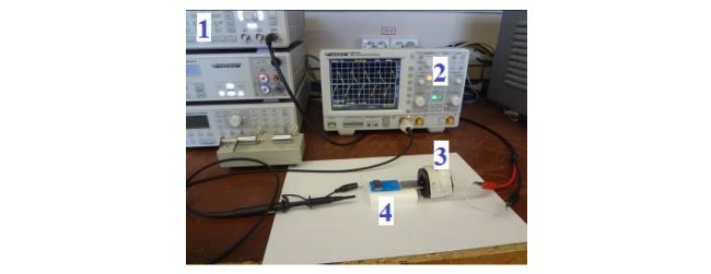
استند شبیه سازی اصل عملیاتی سنسور CKP در شکل 3 نشان داده شده است. استند شبیه سازی شامل ژنراتور HMF2550، اسیلسکوپ HMO722، مغناطیس سنج DX-180، کویل سولنئیدی با عرض 3 cm، قطر داخلی 2 cm، قطر خارجی 4 cm تعداد چرخش های حدود 2000، امپدانس 120 Ohms، هستۀ یک آلیاژ فولادی مغناطیسی نرم، عنصر ME است.
اندازه گیری ویژگی ها و مشخصه ها به شرح زیر انجام می شود. سیگنال ژنرانور به کویل سولنئید داده می شود. میدان مغناطیسی تناوبی در کویل در فرکانس از پیش تنظیم شده شکل می گیرد. این میدان مغناطیسی تناوبی از طریق هستۀ فولادی در اختیار سنسور ME قرار داده می شود. فاصلۀ بین سنسور ME هستۀ فولادی را می توان تنظیم کرد. شبیه سازی حلقۀ دندانه دار فولادی به این شیوه انجام می شود. این روش توسعۀ طراحی سنسور ME بدون استفاده از سخت افزار واقعی و برآورد ویژگی های محدود کنندۀ سنسور را ممکن می سازد. ژنراتور سیگنال با فرکانس 20 Hz دامنۀ 10 V در کویل جهت مطالعۀ ویژگی های سنسور الگوی ME فراهم شد. کویل سولنئیدی باعث انحراف نسبی در سیگنال، و شبیه سازی کار دستگاه های واقعی می شود. سنسور ME سیگنال را تبدیل می کند و سپس این سیگنال به اوسیلوسکوپ می رود. مغناطیس سنج دامنۀ میدان های مغناطیسی ثابت و تناوبی را اندازه گیری می کند. در مورد سنسور توصیف شده در قسمت 2، ما به ویژگی های زیر دست یافتیم. شکل 4 ویژگی بارز سنسور ME برای موردی که شکاف بین هستۀ فولادی و سنسور 1 mm بود را نشان می دهد و شکل 5 همان ویژگی بارز با شکاف 3,5 mm را نشان می دهد.
Abstract
This paper is devoted to the research of possibilities of applying of the magnetoelectric material as the sensing element of a crankshaft position sensor. Proposed magnetoelectric crankshaft position sensor would have several advantages against the traditional sensors such as smaller size and weight. Magnetostrictive-piezoelectric layered structure based on piezoceramic PZT plate with dimensions 0.5 mm of thickness, 30 mm of length and 10 mm of wide was used as an element of a sensor. The designed sensor showed the peak voltage pulse of 1.4 V. Proposed design with using the magnetoelectric material may be applied to creation of position and displacement sensors.
I. INTRODUCTION
Industrial progress in the modern era places the task in the invention of new technical devices and components to them. The automotive industry is one of the important sectors of the economy also undergo unceasing updating, in looking for competitive advantages even in small things, and more so using breakthrough technology. Electronics, computers and sensors have become an integral part of any modern car. For example, almost every auto is equipped with a crankshaft position sensor (CKP sensor) or sometimes also a camshaft position sensor (CMP sensor) [6]. CKP sensor is used to determine the angular position of the crankshaft of the engine, synchronization of the control unit with the workflow engine and determining the rotational speed of the shaft. This gives significant advantages such auto and generally has a consumer demand. The principle of operation of the CKP and CMP sensors is based on the phenomenon of electromagnetic induction or the Hall effect.Magnetoelectric sensors developed recently are a good alternative to inductive sensors and Hall sensors. Magnetoelectric (ME) effect is an effect that is manifested in the change of the electric polarization of the material P under the action of an external magnetic field H (the direct effect) or in the change in the magnetization of the material M under the influence of an electric field E (opposite effect) [1] and can be used to register position of the crankshaft. The dimensionality of ME coefficient which accepted in most modern publications about ME effect is V/(cm⋅Oe). That is, it is the ratio of the voltage on ME element electrodes to ME element thickness and the alternating magnetic field. We have used in the paper this dimensionality of ME coefficient for correct comparison of study results with other works. The magnitude of a constant magnetic field will also be given in Oersteds. The magnetic field sensor described earlier [2] can be used as the basis for such sensor. As an advantage over inductive sensors, it is worth noting a more simple construction, smaller size and weight. In addition, the advantage over the sensors based on the Hall effect is the absence of a special power source required for operation of the sensor. As a prototype of ME CKP sensor and for further improvement of characteristics can be used a current sensor, previously proposed in the papers [3-5]. The principle of operation of ME CKP sensor provides accurate level information about the position of the crankshaft. In principle, proposed the idea of measuring the angular position or the speed of rotation of the shaft with ME element can be used for various devices and designs where there is any movement.
II. MAGNETOELECTRIC MATERIAL PROPERTIES
A. Structure
We applied for the manufacture of CKP sensor magnetostrictive-piezoelectric layered structure. Layered structure based on piezoceramic PZT plate in our case had 0.5 mm of thickness, 30 mm of length and 10 mm of wide. Piezoelectric was polarized in the thickness direction. The electrodes are applied on two sides of the piezoelectric plate. The electrodes are made from three layers of Metglas and correspond in size the PZT plate. Thickness of one layer of Metglas was about 0.02 mm. Joint of layered design was done by gluing. Thus, the total number of thin layers Metglas was 6 with a total thickness of magnetostrictive phase about 0.12 mm. The layered structure is symmetrical. The electrical signal is taken from the surface of Metglas plates. Low-frequency magnetoelectric coefficient in this ME magnetostrictivepiezoelectric structure measured at the frequency about 20 Hz was 0,75 V/(cm⋅Oe). The size of ME element, technology, materials and manner of fastening have a significant influence on the value of ME coefficient.
B. Specifications
ME coefficient is an important characteristic of ME material. It is measured as the ratio of the magnitude of the voltage at the output structure to the structure thickness and to the alternating magnetic field value. The bias of ME material in permanent magnetic field is used to get the best characteristics. Lowfrequency and resonant ME coefficients are distinguished. In our case we use the mode of operation of the sensor outside of the resonance at a low frequency. Typical value of ME coefficient for the structures described above will be from tens to hundreds mV/(cm⋅Oe) when the thickness of a piezoelectric material of about half a millimeter and the magnitude of the alternating magnetic field in the range of a few Oe. Bias field should be tuned to the maximum ME coefficient for layered structures using Metglas which is from 50 to 80 Oe. Fig. 1 shows the dependence of ME coefficient αЕ on the magnitude of the constant magnetic field at the frequency of alternating magnetic field of 20 Hz for the structure described in the previous section.
The choice of optimal AC and DC magnetic fields are very important task for designing sensors.
III. OPERATING PRINCIPLE
The crankshaft position sensor based on magnetoelectric effect works as follows. Fig. 2 shows the scheme of ME CKP sensor. ME element (2) should be located in the immediate vicinity of the steel toothed ring (1). The constant magnetic field H0 (bias field) is created using the permanent magnet (3) located near ME element. Nd2Fe14B magnet with dimensions of 20 mm × 10 mm × 2 mm with a residual flux density of 1 T was used for the prototype. Steel toothed ring has one type of label determined by successive identical combinations of "tooth/interval between the teeth" and the distinguishable labels with increased intervals between the teeth. The magnetoelectric element is experiencing the action of alternating magnetic field H~, caused by the rotation of the steel toothed ring (1) due to the alternation during the rotation of plots with high magnetic permeability – "tooth" and low magnetic permeability – the "interval between teeth". ME sensor for each passing combinations "the tooth/interval between the teeth" generates a pulse with the different levels. The signal has a high level in the locations of teeth, and low level at the locations of all intervals between teeth. The alternating magnetic field H~ and the bias field H0 collinear to each other and perpendicular to the polarization vector P of the piezoelectric layer of ME elements. The conversion of magnetic energy into electric potential in ME element is due to the magnetoelectric effect as result from the interaction of magnetostrictive and piezoelectric components of ME material. Alternating electrical signal proportional to the rotational speed of the crankshaft and depending on the angle of rotation occurs at the electrodes (4)of ME element. ME element and the magnet are placed in the case (5).
IV. SIMULATION STAND
Stand for simulation of the operation principle of CKP sensor is shown in Fig. 3. The simulation stand consists of HMF2550 generator; oscilloscope HMO722; magnetometer DX-180; solenoidal coil with the width of 3 cm, internal diameter of 2 cm, outer diameter of 4 cm, number of turns about 2000; the impedance of 120 Ohms; the core of a soft magnetic steel alloy; ME element.
Measurement of characteristics is performed as follows. The signal from the generator is fed to the solenoid coil. The alternating magnetic field is formed in the coil at a preset frequency. This alternating magnetic field through the steel core is supplied to ME sensor. The distance between ME sensor and the steel core can be adjusted. The simulation of the steel toothed ring is performed in this way. This method makes it possible to develop ME sensor design without using the actual hardware and to estimate limiting characteristics of the sensor. The signal generator with the frequency of 20 Hz and amplitude 10 V was supplied on the coil for study of the characteristics of ME prototype sensor. Solenoidal coil causes a slight distortion in the signal, simulating the work of real devices. ME sensor converts the signal and then this signal goes to the oscilloscope. The magnetometer measures the amplitude of constant and alternating magnetic fields. For the sensor described in section II, we obtained the following characteristics. Fig. 4 shows the characteristic of ME sensor for the case when the gap between the steel core and the sensor was 1 mm, Fig. 5 shows the same characteristic with a gap of 3,5 mm Fig. 6 shows the characteristic when steel core was absent in the coil. As can be seen from the figures, ME sensor has a high sensitivity to AC magnetic field. Maximum output peak-to-peak value voltage was about 270 mV for the above parameters. Data obtained by measurements on this stand allowed us to refine the sensor design.
چکیده
1. مقدمه
2. ویژگی های مادۀ الکتریسیتۀ القایی
الف. ساختار
ب. مشخصات
3. اصل عملیاتی
4. استند شبیه سازی
5. استند اندازه گیری
6. رویکرد نظری
7. نتیجه گیری
منابع
Abstract
1. INTRODUCTION
2. MAGNETOELECTRIC MATERIAL PROPERTIES
A. Structure
B. Specifications
3. OPERATING PRINCIPLE
4. SIMULATION STAND
5. MEASURING STAND
6. THEORETICAL APROACH
7. CONCLUSION
REFERENCES